background image

7.  MAINTENANCE & TROUBLESHOOTING

107

7.  ViX Maintenance and Troubleshooting

Maintenance

ViX drive systems do not require any routine maintenance, but occasional checking of the
following points is recommended.

Motor inspection

Periodically check the motor to ensure that the mounting bolts and couplings are tight.
Check that the motor cables are not being damaged by moving parts and are not being
pulled or forced into tight bends during machine operation.  Check all cable connectors and
particularly the safety earth connection.

Drive inspection

Check that the drives are clear of loose material and that there is adequate clearance to
allow a free flow of air through the ventilation slots.  Check that drive fixings are tight and that
the motor screen connection is secure.

Troubleshooting

IMPORTANT NOTE  -  ensure that power is turned off before any connections are
removed or changed.  Removing a drive with power applied can turn a recoverable fault
situation into a major problem.

WARNING – Risk of damage and/or personal injury

The ViX drives described in this user guide contain no user-serviceable parts.

Attempting to open the case of any unit, or to replace any internal component, may

result in damage to the unit and/or personal injury.  This may also void the warranty.

Содержание ViX250AE

Страница 1: ...ViX250AE ViX500AE Servo Drives User Guide Part No 1600 313 02 August t 2003 For software revision 2 0 onwards...

Страница 2: ......

Страница 3: ...in operation This product is sold as a motion control component to be installed in a complete system using good engineering practice Care must be taken to ensure that the product is installed and use...

Страница 4: ...eed electrical power drive systems this product is of the restricted sales distribution class which meets the needs of an industrial environment when installed as directed However further measures may...

Страница 5: ...lp_emd_OG parker com Website www parker eme com Website www parker eme com For engineering For engineering assistance in Italy assistance in the U S Parker Hannifin SpA Parker Hannifin Corporation Ele...

Страница 6: ...ardware Reference 113 Appendix A 117 Appendix B 119 Index 123 The ViX250AE 500AE Intelligent Digital Servo Drive is UL Recognised under file E194158 This means it may be incorporated into end user pro...

Страница 7: ...ii VIX AE SERVO DRIVE USER GUIDE Latest Changes Sheet This page lists important changes occurring immediately before publication or between issue updates...

Страница 8: ...compact case the drives are suitable for either direct panel or DIN rail mounting Using full PWM control with sinusoidal commutation the two versions of power stage can have continuous current ratings...

Страница 9: ...dback ViX500AE 500VA Servo with encoder resolver feedback Table 1 1 ViX250 ViX500 Digital Servo Drive Options Product Features Protection Circuits Motor short circuits Over voltage Under voltage Drive...

Страница 10: ...plastic bag 5006 211 1 Product label 5006 211 1 Product label 0405 811 1 10 way Flange plug strip 0405 811 1 10 way Flange plug strip 0405 961 1 9 way D type plug 0405 961 1 9 way D type plug 0405 962...

Страница 11: ...th understanding of drive applications and motion control consider attending one of our world wide Customer Specific Training Workshops Examples of previous courses that have proved to be of benefit i...

Страница 12: ...cally in an area where there is at least a 50mm minimum air gap above and below the package and a 10mm minimum gap either side Avoid mounting heat producing equipment directly below a drive Installers...

Страница 13: ...USER GUIDE Drive Dimensions ViX250 and ViX500 drives share the same dimensions shown in Figure 2 1 4 5 98 5 with connector 21 4 5 88 1 42 3 10 1 124 7 135 145 5 X1 X3 X4 X5 X2 HVSTFB Figure 2 1 ViX25...

Страница 14: ...N rail by hooking the top of the bracket over the top of the DIN rail and gently pushing the drive forward to engage the lower section of the bracket Remove the bracket by inserting a flat bladed scre...

Страница 15: ...e combination without first securing the motor see the Safety Warning at the front of this user guide CAUTION risk of equipment damage Do not back drive the motor that is use the motor in an applicati...

Страница 16: ...Cabinet Installation To produce an EMC and LVD compliant installation we recommend that drives are mounted within a steel equipment cabinet This form of enclosure is not essential to achieving EMC com...

Страница 17: ...ay connector Figure 3 1 X1 Power Connections WARNING Possible drive damage If you use Parker XL Series stepper drives do not attempt to use any power wiring harness taken from an XL drive Although the...

Страница 18: ...upply Current Supply Capacitance ViX500 6 3A RMS 6600 F ViX250 2 5A RMS 3300 F Table 3 2 Drive Supply Currents 24V Requirements Both drive types require a 24V controller and logic supply The supply to...

Страница 19: ...ments A single axis using a ViX250 or possibly a lightly loaded dual axis application may be powered using an XL PSU This switching supply has a power rating of 250W and can supply 3 1A continuous 7 5...

Страница 20: ...otor rpm Nm PEAK CONT 5 0 4 0 1 0 2 0 3 0 0 1000 0 1500 2000 2500 ViX500 with BE341G motor rpm Nm 1 5 1 0 0 5 0 1000 0 2000 3000 4000 5000 PEAK CONT 6000 7000 ViX500 with BE163F motor rpm Nm 6 5 4 1 2...

Страница 21: ...hout the need for an EMC mains input filter see note 2 The use of the XL PSU offers the following benefits Auto adapts to supplies between 95 and 264V AC No external EMC filter required Compact size B...

Страница 22: ...10V 230V 50 60 Hz 250VA Power Supply Unit XL GND EXT BRAKING RES DC 80V HV STATUS BRAKING RES 24V STATUS X2 X3 X1 X4 X5 ST HV FB 10 1 10 1 10 mm Mininum spacing between drives PSU L N EARTH GND The XL...

Страница 23: ...th the top 4 5mm diameter fixing hole and the bottom two 4 5mm width fixing slots should be used Allow a minimum free space of 50mm both below and above its case and 10mm free space on both sides Do n...

Страница 24: ...n HV supply separately to each drive The lower current requirements of the 24V logic brake supply can allow the wiring to be linked between drives For full installation instructions see the PL1100 Pow...

Страница 25: ...d Assuming the use of an equipment cabinet locate the EMC filter and transformers in the base of the cabinet and route AC supply cables up to the PL1100 Attempt to layout the wiring in a way that mini...

Страница 26: ...DC OUT Risk of electric shock High voltage remains on terminals after power is removed Allow 5 minutes for capacitors to discharge EXT BRAKING RES MOTOR 0V X1 X1 X2 MOTOR HV OUT HV REGEN 24V PE 0V CA...

Страница 27: ...s motors choose the appropriate connector option to ensure the temperature sensor output is made available on the required connector BE nMSn SM nGSn Motor power cables are identified using the number...

Страница 28: ...cally strong fixing If you have a ready made ViX PWR XXXX cable use the pre fitted P clip otherwise use one of the clips listed below Size Parker part number Comments 9mm ID 4216 101 10 7mm ID 4216 10...

Страница 29: ...entification Drive end identity X1 Motor connector pin number Function 4 black 1 Phase U 3 black 2 Phase V 2 black 6 Phase W 7 black via fuse 4 Brake 1 black 5 Brake 5 green yellow 3 Gnd Table 3 5 Mot...

Страница 30: ...in 6 Table 3 6 Motor Feedback Cable Wiring The 15 way D type connector will require the feedback cable screen to be bonded to the metal connector shell as shown in Figure 3 9 Earth bonding area in cov...

Страница 31: ...bsorbers motor wiring details There must be no break in the 360 coverage that the screen provides around the cable conductors Use of a through connector must retain the 360 coverage possibly by the us...

Страница 32: ...east 300mm away from I O cables carrying control signals Motor Phase Contactors We recommend that motor phase contactors are not used within the motor power cables As an alternative make use of the dr...

Страница 33: ...ype Motor Rated Current in Amps Motor Inductance in mH per phase ViX500 ViX250 BE231GX XXXX 5 3 4 4 BE341GX XXXX 5 2 16 5 BE341JX XXXX 7 4 7 1 SMB60 XX 6 7 3 6 SMB82 XX 10 5 3 4 Table 3 7 Optimum Moto...

Страница 34: ...he drive electronics after the encoder signal has been processed Rated speed shaft speed in rpm for a rotary servo Resistance resistance of a single phase winding measured line to line in Ohms Inducta...

Страница 35: ...8 VIX AE SERVO DRIVE USER GUIDE The Optional Parameters Tab Selecting the optional parameters tab gives you access to the screen shown in Figure 3 12 Figure 3 12 EASI V Custom Motor Optional Parameter...

Страница 36: ...e separate dissipation parameters and comparing them to their individual I2t thresholds These dissipation parameters are Motor I2T protects the motor from drive output current above the rated motor cu...

Страница 37: ...equired In this case set the thermal time constant of the motor to zero see MOTOR command Motor Voltage Ratings Motors with a withstand voltage rating from phase to earth of 1000V AC should be used An...

Страница 38: ...7 7 8 8 9 9 10 10 11 12 13 14 15 16 17 18 19 20 0 Time to trip I2t circuit in seconds ViX250 I2t function moving ViX250 demanded phase current in A rms Figure 3 13 ViX250 I2t function moving 0 1 2 2 4...

Страница 39: ...ViX500 I2t function moving ViX500 demanded phase current in A rms Figure 3 15 ViX500 I2t function moving 0 2 2 4 4 6 6 8 8 10 1 12 1 2 14 1 4 16 1 6 18 1 8 20 2 2 2 2 4 2 6 2 8 3 3 2 3 4 3 6 3 8 4 0...

Страница 40: ...Tx Reserved RS232 Tx D loop do not connect 5V output Incremental enc Z Incremental enc Z GND reserved reserved 1 2 3 4 5 6 7 8 9 10 11 12 13 14 15 X2 Function Feedback encoder 5V output GND Increment...

Страница 41: ...24V DC 6 0V GND for 24V DC 5 Motor Earth 4 Motor phase U 3 Motor phase V 2 Motor phase W 1 Motor brake Table 3 8 X1 Power and Motor Connections Motor Connections at the Drive Refer to the EMC install...

Страница 42: ...1 of X1 to ground using the manual BRAKE command X1 24V DC 24V DC SUPPLY MOTOR BRAKE IN ITS RELEASED OR ENERGISED STATE 9 2A FUSE recommended 8 7 6 5 4 3 2 BRAKE 10 1 Power motor 10 way connector Figu...

Страница 43: ...REFres reserved 5 5V output 5V output 6 GND GND 7 SIN Incremental enc A 8 SIN Incremental enc A 9 reserved Commutation f b A0 10 Motor overtemp Motor overtemp 11 COS Incremental enc B 12 COS Incremen...

Страница 44: ...nd the torque vector set to be at the middle of the commutation segment Whilst rotating as soon as a commutation encoder edge is observed the torque vector is realigned more accurately After the first...

Страница 45: ...nectors X6 and X7 may also be used for inter drive communications where multi axis systems are used RS485 Operation RS485 operation is only possible on drives fitted with the appropriate FEM Fieldbus...

Страница 46: ...will not be overwritten until a save command is issued 1 5 PC RS232 socket Interface X3 Socket Serial connector plug Serial connector socket Back of mating plug Back of mating plug Back of mating soc...

Страница 47: ...sy Chain later in this section RS232 Connecting Leads RS232 cables can be ordered from Parker Various lengths are available as listed in Table 3 11 Part Number Length RS232 EASI 0250 2 5m RS232 EASI 0...

Страница 48: ...D type socket Connector Pin Out Connector Pin X4 Encoder I O 1 ANA1 input 2 ANA1 input 3 0V 4 Z index out 5 Z index out 6 Fault output 11 Energise input Energise See system variable ES Table 3 12 X4...

Страница 49: ...der I O Circuit Details Differential Analogue Input Control of the ViX base drive is via a differential analogue input The input circuit shown in Figure 3 21 can interface to an external 10V different...

Страница 50: ...alogue Differential Input Characteristic Fault Output The fault output is an independent NPN open collector output which is normally low active high The output ratings are 30V maximum in the OFF condi...

Страница 51: ...or Type Connector type is a high density 15 way D type plug Connector Pin Out Connector Pin X5 Input Output 1 0V 2 0V 3 0V 4 Reserved 5 Reserved 6 Reserved 7 Reserved 8 Reserved 9 Reserved 10 Brake IN...

Страница 52: ...transistor off will engage the brake and an active pull down to a logic 0 transistor on will release the brake Driving the input with a low level logic output a logic 1 transistor on will engage the b...

Страница 53: ...of the output 1K2 X5 pin 15 0V TL074CD Drive Analogue monitor output Figure 3 25 Analogue Monitor Output RJ45 Interfaces Positioned beneath the drive are two RJ45 communication interfaces X6 and X7 T...

Страница 54: ...ed White Green 4 RS232 Gnd Blue 5 RS232 Gnd White Blue 6 Reserved Green 7 RS232 Tx White Brown 8 Rs232 Rx Brown X7 1 RX TX RS485 White Orange 2 RX TX RS485 Orange 3 Reserved White Green 4 RS232 sense...

Страница 55: ...g commands 1 cause the 1 st drive to establish the daisy chain in a 3 axis system the response will be 4 0SV save the address configuration 0Z reset response should be a single check sum from axis 1 m...

Страница 56: ...RJ45 link cables can be ordered from Parker Various lengths are available as listed in Table 3 15 Part Number Length VIX RJ45 0025 0 25m VIX RJ45 0050 0 5m VIX RJ45 0075 0 75m VIX RJ45 0100 1 0m VIX R...

Страница 57: ...50 VIX AE SERVO DRIVE USER GUIDE...

Страница 58: ...ommands to the drive and to receive status information back Direct Mode Direct operation of the drive is possible over a serial link from a PC or PLC When used directly the drive will accept commands...

Страница 59: ...DF Drive Fault status Y N See reporting of drive faults DF1 2 3 4 EI Encoder Input Y Y 0 step dir default 1 cw ccw 2 quad ABZ de energise drive to change EO Encoder signal Output Y Y 0 step dir 1 cw c...

Страница 60: ...1023 default 250 motor definition dependent PA Position Actual Y N 2 147 483 648 to 0 to 2 147 483 647 default 0 PC Peak Current Y Y Sets maximum drive output value scaling factor 100 400 of MC defau...

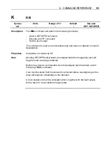
Страница 61: ...or torque being generated by the drive depending upon the setting of system variable AM Setting AM to 2 generates a bipolar triangular waveform with a time period of 1 second BR Description This sets...

Страница 62: ...STEP CW A 7 STEP CW A 13 DIR CCW B 8 DIR CCW B Table 4 3 Encoder Input Configuration CAUTION De energise the drive before changing EI and EO ES Description System variable ES controls the required po...

Страница 63: ...ortional gain gives a stiff responsive system but results in overshoot and oscillation that require damping GV Description Velocity feedback is a signal which increases with shaft speed It acts in a n...

Страница 64: ...nt in mode position MP RV Description Reports the revision of software being used by the controller SN Description Reports the serial number of a drive ST Description See reporting of status bits in R...

Страница 65: ...Motor energised 10 Motor undefined use MOTOR command 16 Duty cycle too high excessive motor current I2t 23 Tracking limit is greater than max allowed position error 24 Last SETUPFB command failed 25...

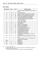
Страница 66: ...ause the Drive LED to turn RED Once the fault has been corrected the drive may be re energised using the ON command When read DF reports a 32 bit double word pattern of the form 0000_0000_0000_ 32 bit...

Страница 67: ...er stage 16 K T Controller diagnostic failure 17 K R Output stage over current 18 C R Output driver over current 19 C R Tracking limit exceeded while in motion is a latched fault 20 K R Velocity excee...

Страница 68: ...condition User Fault Byte Reporting In exactly the same way as the status variable the user fault status can be reported a byte at a time using UFn within a read command For example to read or test th...

Страница 69: ...VIX AE SERVO DRIVE USER GUIDE 62 Servo Control Loop GF GP FT 1 Torque Demand 2 Position Feedback GI dt Position Demand GV d dt d dt Figure 4 1 ViX Servo Control Loop...

Страница 70: ...ase servo torque mode Base servo velocity mode Base servo position mode This mode uses the servo step and direction inputs to control the drive Figure 4 2 shows a 6K controller used for step direction...

Страница 71: ...24V DC Commands For the ViX drive issue the following commands 1MP Mode Position Step Direction 1W ES 0 Energise input active level 1W EI 0 Set input for step direction 1SV Save settings A valid MOTOR...

Страница 72: ...e inputs to control the drive Figure 4 3 shows a 6K controller used for control purposes A double multi core cable links the 6K and ViX with the connections listed in Table 4 8 X2 X3 X1 X4 X5 ST HV FB...

Страница 73: ...the 6K should be connected to 24V DC Velocity Mode Commands For the ViX drive issue the following commands 1MV Mode Velocity 1W ES 0 Energise input active level 1SV Save settings A valid MOTOR comman...

Страница 74: ...ngs A valid MOTOR command is required All GAINS need to be 0 0 For the 6K4 issue the following commands AXSDEF1111 All axes are steppers ERES8000 8000 8000 8000 Should match ViX motor resolution DRFLV...

Страница 75: ...olds position while the brake is released and the brake holds position before the drive is de energised Figure 4 4 shows the operation of the two timers RD Drive ON issued Drive OFF issued ED Brake st...

Страница 76: ...ation of the brake could lead to physical damage of the brake components Default Brake Command For the base drive the BRAKE default setting is all brake modes disabled Other Factors that Influence Bra...

Страница 77: ...s fitted 24V Power Failure A dip in the 24V supply will turn off the drive s controller which in turn will apply the brake Cycle the 24V supply to re start the controller If you expect this to happen...

Страница 78: ...of charge from our Website www parker eme com Serial Link Lead You will need a 2 wire plus ground lead which has the Rx and Tx wires crossed over Wiring details are given in the Electrical Installatio...

Страница 79: ...ation terminate all applications currently running A step by step installation of Easi V software follows 1 Place the Easi V CD in your PC s CDROM drive 2 Once loaded the CD should auto start If this...

Страница 80: ...ct NEXT to begin file transfer 7 Once Easi V has been loaded the screen will display a message dialogue box stating Setup is complete You may run the installed program by double clicking on the progra...

Страница 81: ...hen using rotary motors make the selection shown Figure 5 3 Easi V Product Selection Selecting Product from the Utilities menu will also display the product selection screen Selecting OK will display...

Страница 82: ...lighted text to clipboard Copy highlighted text to clipboard Paste contents of clipboard to current cursor location Delete highlighted text Highlight all text in active editor file window Go to a part...

Страница 83: ...ay status bits or messages Download program to drive F4 Download program Upload program Displays LED diagnostics sheet colour flash rate Windows Window controls Share program desktop space between ope...

Страница 84: ...described in the Electrical Installation section WARNING To avoid causing damage to a PC serial port the drive must be earthed before making any serial connections Connect the RS232 lead between the...

Страница 85: ...refer to the Troubleshooting Section Note The baud rate selected must agree with the drive s hardware selected value Configure Terminal Buttons The Terminal menu has a Configure terminal buttons F2 co...

Страница 86: ...ending upon the skill and experience of the operator Guided servo setup guides you through setup for a particular motor type quick and simple Servo setup allows text entry of motor parameters for expe...

Страница 87: ...DRIVE USER GUIDE 80 From the drop down menu select your motor type or perform a custom set up Click Next Select the operating mode of the drive and the direction of rotation required for a rotary moto...

Страница 88: ...nt ration PC For a pre defined motor type use the default value displayed Keep the Current Clamp CL value as 100 Click Next This screen allows adjustment of the drive s gain parameters For drive testi...

Страница 89: ...t High logic level 24V source IC 256 upper box ticked lower blank default High logic level 24V sink IC 257 upper and lower boxes ticked Low logic level 5V source IC 0 no boxes ticked Note Upper box bl...

Страница 90: ...S ticked ES 1 the drive is energised without any connection being made between X4 pin 11 and X4 pin 3 or 4 This screen indicates the completion of the guided servo setup Clicking on the Create a setup...

Страница 91: ...r Tab of Servo Setup The buttons displayed along the base of this screen can be used as follows Upload retrieves the current settings for the selected axis Download updates the current axis with your...

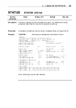
Страница 92: ...splayed as text messages within the Status Report window as shown in Figure 5 7 This eliminates manual decoding errors and gives an immediate update of the drive s status Figure 5 7 Reporting Status o...

Страница 93: ...n line help facilities which allows you to search for help on a particular topic either within the main contents or by entering a topic string All the commands listed within this user guide are availa...

Страница 94: ...nd with the address 0 To prevent spurious feedback any report or read command using address 0 will be ignored Note a drive will ignore a command missing an address prefix Where commands such as R and...

Страница 95: ...e return A space is not valid 2 A command must not contain any space characters 3 All commands are device specific that is they always need an address 4 For reasons of clarity program examples appear...

Страница 96: ...and just sent and any other interrogation commands get buffered and will not report back until the current function is finished In this situation Immediate only commands can be executed Saved by SV A...

Страница 97: ...se after the drive has energised Range is 0 to 5000 milliseconds default 50ms ED is the time in milliseconds for the brake to engage before the drive de energises Range is 0 to 5000 milliseconds defau...

Страница 98: ...edback GF Gain Feedforward GI Gain Integral action FT Filter time constant For ranges see the system variables list Properties Immediate saved by SV Notes The only gains used in calculating the positi...

Страница 99: ...ored Properties Immediate saved by SV Note The drive must be de energised for the H command to be executed If the command is issued whilst the drive is energised an error message will be generated and...

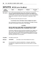
Страница 100: ...deceleration Properties Immediate not saved by SV Note Aborting SETUPFB will prevent an energise state from happening and will flag the motor as being undefined Motion may only be commanded once the e...

Страница 101: ...nalogue velocity input Properties Immediate saved by SV Example 1 The code below sets up for torque demand 3MT mode torque To check the current mode type 3M The response will be MT Note The drive must...

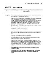
Страница 102: ...g resistance in Ohms Inductance Winding inductance in mH KT Torque constant of the motor Nm A Note Thermal time constant is the time in seconds for the motor to reach two thirds of its rated temperatu...

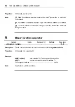
Страница 103: ...ot be allowed to energise without a valid motor command being executed R Report system parameter Syntax Units Range of n Default See also aR system_variable W R Description The R command allows the us...

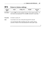
Страница 104: ...alises the drive to factory default settings The drive must be de energised OFF for the RFS command to be executed Properties Immediate saved by SV Note The address is set to axis 1 after performing a...

Страница 105: ...display a message indicating the nature of the problem followed by a FAIL message CAUTION DO NOT COUPLE ANY MACHINERY TO THE MOTOR SHAFT WHILE RUNNING THIS COMMAND AS SHAFT MOVEMENT WILL OCCUR Correc...

Страница 106: ...ard revision 2 Servo drive Power card revision 3 Servo power stage E500 Motor type undefined FPGA_ID read 1070 FPGA_ID file 1070 MOTOR TYPE 0 RESOLUTION 4000 CONT STALL CURRENT 0 1 Amps POLES 8 PEAK C...

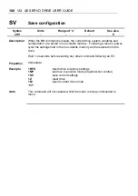
Страница 107: ...g a reset or power cycle the settings held in the non volatile memory will be restored into the drive Wait 1 2 seconds before sending any other command following an SV Properties Immediate Example 1RF...

Страница 108: ...2W TL 4000 2R TL 4000 Note The drive will need to be de energised before certain system variables can be written to See also R command See table of allowable variables for individual parameter details...

Страница 109: ...ive faults DF1 2 3 4 EI Encoder Input Y Y 0 step dir default 1 cw ccw 2 quad ABZ de energise drive to change EO Encoder signal Output Y Y 0 step dir 1 cw ccw 2 quad ABZ default de energise drive to ch...

Страница 110: ...Index Pulse Y Y 0 to 1023 default 250 motor definition dependent PA Position Actual Y N 2 147 483 648 to 0 to 2 147 483 647 default 0 PC Peak Current Y Y Sets maximum drive output value scaling facto...

Страница 111: ...over temperature 13 C R Drive over temperature 14 K T Incompatible firmware version 15 K T Unrecognised power stage 16 K T Controller diagnostic failure 17 K R Output stage over current 18 C R Output...

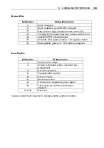
Страница 112: ...for positive motion 1 for negative motion 26 Brake applied goes to a 1 if the brake is engaged User Faults Bit Number UF Information 1 Value is out of range 2 Incorrect command syntax command has wro...

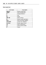
Страница 113: ...E Brake configuration GAINS Gains configuration H Change direction K Kill M Mode MOTOR Motor settings R Report system parameter RFS Return to factory settings SETUPFB Setup motor feedback STATUS Repor...

Страница 114: ...nspection Check that the drives are clear of loose material and that there is adequate clearance to allow a free flow of air through the ventilation slots Check that drive fixings are tight and that t...

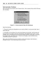
Страница 115: ...rial COM port 2 An RS232 communications link can be loop tested by removing the communications D type plug where it connects to the drive and placing a short between pins 4 and 5 In this condition any...

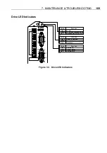
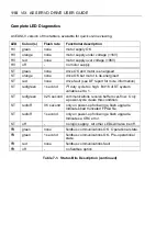
Страница 116: ...6 1 1 1 5 5 Red Feedback fault with no HV Orange HV OK and feedback fault Green HV OK Colour Function Red Drive fault Orange Drive OK but de energised Green Ready energised Colour Function Red Comms...

Страница 117: ...on ST red green 1 second I2t duty cycle too high Bit 16 of ST system variable set to 1 ST red green 0 25 second communications receive buffer over flow Only a power cycle clears this condition ST red...

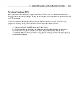
Страница 118: ...force a hardware RFS follow the procedure detailed below note you will loose any program in memory and system variables will return to their default values 1 Connect X3 pin 2 MODE input to X3 pin 3 0V...

Страница 119: ...arker without prior authorisation Repairs will be carried out by Parker but will be processed via your supplier Parker may at their discretion authorise direct shipment to and from Poole Offenburg or...

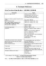
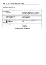
Страница 120: ...voltage 98V nominal Drive over temperature Motor over temperature motor dependent 24V reverse polarity Commutation encoder fault Resolver fault Temperature protection motor protection depends upon th...

Страница 121: ...top bit no parity optional echoback Xon Xoff supported Baud rate 9600 or 19 200 Address setting range 1 255 by software RS232 connection 2 wire plus ground Brake Input Input levels Logic high 14 24V l...

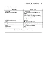
Страница 122: ...40 C to 50 C with forced air cooling of minimum 0 5m s entering the base of the drive approximately 3 5m3 h or 2cfm airflow through the cabinet Storage temperature range 20 to 70 C Humidity 95 max non...

Страница 123: ...116 VIX AE SERVO DRIVE USER GUIDE...

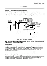
Страница 124: ...h screen X1 9 X1 8 Figure A 1 Drive Power Supply Note The saftey earth must be reliably earthed at X1 8 The DC input should also be connected to earth at a convenient point Supply Wiring Use approved...

Страница 125: ...ons will give a useful guide to the final specification required Fuses Fuses should be time delay high breaking capacity and should be rated for the number of drives and expected in rush current AC Fu...

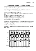
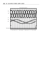
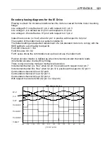
Страница 126: ...voltage V U is defined as X1 pin 3 with respect to X1 pin 4 Line voltage U W is defined as X1 pin 4 with respect to X1 pin 2 Cos is defined as X2 pin 12 with respect to X2 pin 11 Sin is defined as X2...

Страница 127: ...120 VIX AE SERVO DRIVE USER GUIDE 90 180 270 0 90 180 270 0 90 180 270 0 90 180 270 0 Drive Z index Sin Cos V U U W W V BE resolver phasing diagram...

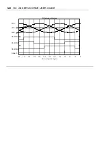
Страница 128: ...ting to avoid having to adjust IX For SME motors IX 150 For BE motors IX 90 For H series drives the commutation set up does not use the index mark Positive encoder rotation is defined as when incremen...

Страница 129: ...122 VIX AE SERVO DRIVE USER GUIDE 0 30 60 90 120 150 180 210 240 270 300 330 360 BE phasing diagram electrical postion degrees W V V U U W CommA0 CommA1 CommA2 IndexZ...

Страница 130: ...able screening 21 Capacitance of supply 11 Clean earth 9 Command address requirements 87 label multi parameter syntax 88 presentation 87 reference 87 simple syntax 87 Command checking 89 Command list...

Страница 131: ...coder specification 37 Forcing a hardware RFS 111 FT system variable 56 Function indicators 2 Functional specification 113 G GF system variable 56 Goto line number box 75 GP system variable 56 Guided...

Страница 132: ...onal gain 56 Protection circuits 2 Protection class 115 PSU discrete design 117 R R report system parameter 96 RD operation 68 Reset to RS232 mode 39 Resolver compatibility 36 Resolver interface speci...

Страница 133: ...escriptions 61 105 reporting 61 User faults 59 Utilities menu 76 V Velocity gain 56 ViX supply current 11 supply volts 11 ViX250 500 drive dimensions 6 W W write system variable 101 Weight 115 Welcome...

Страница 134: ...it to the number given below Alternatively you may phone or email the correction Name of user guide Part number 1600 _ _ _ _ _ Found on the title page in the bottom left corner Your name Contact numbe...

Страница 135: ......
Страница 136: ...ommunications RS232 Tx Reserved RS232 Tx D loop do not connect 5V output Incremental enc Z Incremental enc Z GND reserved reserved 1 2 3 4 5 6 7 8 9 10 11 12 13 14 15 X2 Function Feedback encoder 5V o...

Отзывы: