VIX AE SERVO DRIVE USER GUIDE
68
Brake Operation
ViX drives have the ability to control a motor holding brake via the X1 pin 1 motor brake
output. Note, special conditions apply to the brake wiring depending upon the brake supply
used, see Motor Brake Control Wiring in the Electrical Installation section.
Before describing the various braking modes, note the following assumptions:
•
The automatic brake functions only operate if a motor with a brake has been set up using
the MOTOR command.
•
The brake output is not controllable by software when the drive is initially powered-up,
whilst in the process of resetting or when powered off. Under these conditions the brake
output should be off and the brake, therefore applied.
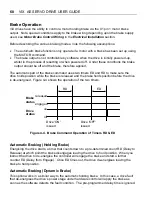
The automatic part of the brake command uses two timers ED and RD to make sure the
drive holds position while the brake is released and the brake holds position before the drive
is de-energised. Figure 4-4 shows the operation of the two timers.
RD
Drive 'ON'
issued
Drive 'OFF'
issued
ED
Brake
status
engaged
on
off
released
Drive
status
Figure 4-4. Brake Command Operation of Timers RD & ED
Automatic Braking (Holding Brake)
Energising the drive starts, a timer that counts down to a pre-determined count RD (Delay to
Release) at which point the brake disengages leaving the drive to hold position. When you
instruct the drive to de-energise the controller will engage the brake and start a further
counter ED (Delay from Engage). Once ED times out, the drive de-energises leaving the
brake to hold position.
Automatic Braking (Dynamic Brake)
This option works in a similar way to the automatic holding brake. In this case, a drive fault
that de-energises the drive’s power stage under hardware control will apply the brake as
soon as the software detects the fault condition. The pre-programmed delay time is ignored.
Содержание ViX250AE
Страница 2: ......
Страница 57: ...50 VIX AE SERVO DRIVE USER GUIDE...
Страница 123: ...116 VIX AE SERVO DRIVE USER GUIDE...
Страница 135: ......

