VIX AE SERVO DRIVE USER GUIDE
52
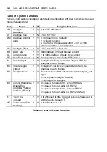
Table of System Variables
Table 4-1 lists system variables in alphabetic order together with their read/write status and
range of values stored.
Var
Name
R
W
Range/default value
AB
Analogue
Deadband
Y
Y
0 to +255, default = 0
AI
Analogue Input
Y
N
-2047 to +2047
AM
Analogue Monitor
Mode
Y
Y
0 = torque monitor (default)
1 = velocity monitor
2 = outputs a triangular waveform –10V to +10V
amplitude, with a 1 second period
AO
Analogue Offset
Y
Y
-2047 to +2047, default = 0
BR
BAUD rate
Y
Y
9600 (default) or 19200 bits per second
CL
Current Clamp
Y
Y
1 to 100% (default) of peak drive current
DF
Drive Fault status
Y
N
See reporting of drive faults DF1,2,3 & 4
EI
Encoder Input
Y
Y
0=step/dir (default), 1=cw/ccw, 2=quad ABZ, de-
energise drive to change
EO
Encoder signal
Output
Y
Y
0=step/dir, 1=cw/ccw, 2=quad ABZ (default), de-
energise drive to change
ES
Energise Sense
Y
Y
Sets the sense of the external energise/energise_bar
signal
0=low signal to energise (default)
1=high signal to energise
EX
Comms. Response
Style & Echo
Control & Physical
Interface (RS232)
Y
Y
0= speak when spoken to, echo off, RS232
1= speak whenever, echo off, RS232
2= speak when spoken to, echo on, RS232
3= speak whenever, echo on, RS232 (default)
FT
Filter Time
constant
Y
Y
0 to 255 used to filter high gain systems, measured in
arbitrary units, default = 0
GF
Feedforward Gain
(tracking)
Y
Y
0 to 1023 default = 5
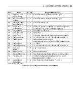
Table 4-1. List of System Variables
Содержание ViX250AE
Страница 2: ......
Страница 57: ...50 VIX AE SERVO DRIVE USER GUIDE...
Страница 123: ...116 VIX AE SERVO DRIVE USER GUIDE...
Страница 135: ......

