


3.5 ISOLATE THE DRIVE
using branch circuit protection or circuit breaker (
8
). Install the 3-phase fuses (
6
). Re-instate
branch circuit protection or circuit breaker (
8
)
IMPORTANT
Do not change any of the previously made calibration settings once the main contactor is energised.
MAIN & AUXILIARY POWER ARE CONNECTED AT THIS STAGE
3.6
Use a Voltmeter that conforms to IEC 61010 (CAT III or higher).
•
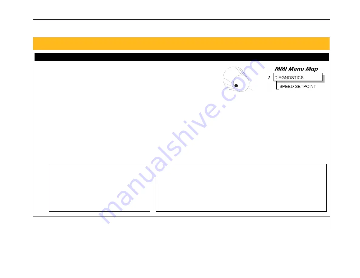
Set the uni-directional speed potentiometer to zero
(check that the value of SPEED SETPOINT parameter = 0 %)
•
Apply the "Start/Run" command to C3.
•
Ensure that "Enable" (C5) is ON.
0
+100
Zero speed =
Terminal A1,
0V input
•
Check that 3-phase mains is applied to the power terminals L1, L2 and L3.
•
Check the correct field voltage appears between the field output terminals D3 and D4.
This is high voltage DC.
Proceed with caution.
•
If the Field Voltage is incorrect do not continue. Switch off all supplies and check connections.
3.7
Check that all six MMI LEDs are now lit, indicating that the motor is capable of rotating.
START (C3 = 24V)
The drive can run provided that:
B8 & B9 are TRUE (+24V)
C5 “Enable” is ON (+24V)
MAIN CURR. LIMIT
≠
0
Speed Setpoint
≠
0
STOP (C3 = 0V)
At 20% setpoint:
the 590C drive (4Q)
can stop in approximately 2 seconds (the drive
decelerates the motor to zero speed at a rate determined by the
STOP TIME and MAIN CURR.LIMIT parameter values)
the 591C drive (2Q)
can coast stop


