DOC-0017-04-EN: AC20 Series - Hardware Installation Manual
DOC-0017-04-EN-A 22.03.2023
79 (154)
•
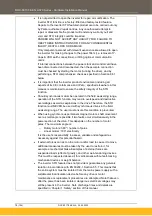
The STO function must not be used for electrical isolation of the
inverter and power. Whenever any personnel require to work on the
drive, associated motor or other power items, they must always use
recognised and suitable electrical isolation devices.
•
The STO0V terminal must be connected to earth at one common point
in the drive system. For multi-drive systems this can be a shared earth
point.
•
The STO serial communications or display messages relating to
accessing or viewing any safety monitoring statuses are for information
only and should not be relied on. They are not part of the drive module
safety system and its associated PL/SIL declared ratings. Any
customer use of these must be appropriately risk assessed in
accordance with the relevant standards or regulations.
•
The STO safety function must be tested regularly - at least once a
week (see Section 8.6.3 below). The comprehensive test must be
completed once a year (see section 8.6.1 below).
•
When using an external safety control unit with adjustable time delay,
for example when implementing an SS1 function, the time delay must
be protected to prevent unauthorised adjustment. The adjustable time
delay on the safety control unit must be set to a value greater than the
duration of the braking ramp controlled by the inverter with maximum
load inertia and from maximum speed. Any external forces must also
be considered, e.g. effects due to gravity.
•
During the active braking phase of SS1 or Stop category 1 (controlled
stop with safely monitored time delay according to EN60204-1), faulty
operation of the drive must be allowed for. If a fault in the drive system
occurs during the active braking phase, the load may coast to an
unguided stop or might even actively accelerate until expiration of the
defined time delay. It is not the remit of this document to specify these
measures. This is for the user to assess.
•
It is the user’s responsibility to ensure that their overall control
implementation recovers safely from supply loss or dips.
•
In all instances it is the user’s responsibility to formally perform suitable
risk assessments and invoke and fully validate the necessary risk
reduction measures after having thoroughly understood the
application, the drive product, and its features. Of special relevance is
to assess the risk of the two STO user inputs shorting together.
•
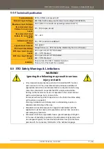
There is maximum cable length of 25m for the STO inputs allowed.
8.6 STO Functional Checks
Two levels of STO functional checks are required periodically:
- Comprehensive check
- Regular check
The user / machine builder must determine the frequency of these checks based on their knowledge, use of
the machine, appropriate standards and any legal requirements.
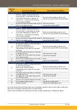
When STO becomes active during any test, power to the motor must be seen by the user to be quenched
instantaneously (the inverter should respond in less than 15 milliseconds).
All STO checks should be performed after the inverter has been commissioned for speed control.
Содержание AC20 Series
Страница 148: ...DOC 0017 04 EN AC20 Series Hardware Installation Manual 148 154 DOC 0017 04 EN A 22 03 2023 Frame 3 Frame 4...
Страница 150: ...DOC 0017 04 EN AC20 Series Hardware Installation Manual 150 154 DOC 0017 04 EN A 22 03 2023 Frame 3...
Страница 151: ...DOC 0017 04 EN AC20 Series Hardware Installation Manual DOC 0017 04 EN A 22 03 2023 151 154 Frame 4 Frame 5...
Страница 152: ...DOC 0017 04 EN AC20 Series Hardware Installation Manual 152 154 DOC 0017 04 EN A 22 03 2023 Frame 6 Frames 7 8...
Страница 153: ...DOC 0017 04 EN AC20 Series Hardware Installation Manual DOC 0017 04 EN A 22 03 2023 153 154 Frame 9 Frame 10...
Страница 154: ...DOC 0017 04 EN AC20 Series Hardware Installation Manual 154 154 DOC 0017 04 EN A 22 03 2023...


