Page 6 of 16
Remove the rudder from the plan and sand all edges to a rounded profile.
The rudder will be hinged to the vertical stabilizer pieces by taping it into place after the parts are
covered. In order to achieve proper surface movement, the mating edges must be sanded to a bevel
shape as shown on the drawing (refer to the Control Surface Detail). Sand a bevel into one side of
the rudder and into the matching side of the two vertical stabilizer pieces as shown on the drawing.
Build the left fuselage side (note that the parts for each side are identical, take care to build
opposite sides!):
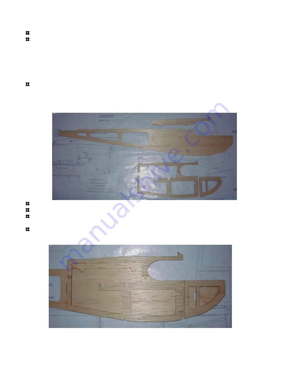
Remove the fuselage sides and fuselage doublers from the sheets. Note that there are two pieces to
each fuselage side and 3 pieces to each side doubler. The doublers can break next to the servo rail
cutouts, so handle with care. If they break, simply align them over the plan and lightly glue the
break. Once they are glued to the fuselage sides in the below steps they will be quite strong.
Glue the upper fuselage section to the lower section. The parts notch together.
Glue the upper doubler section to the lower section. The parts notch together.
Glue the doubler to the inside section of the fuselage, make sure all sides are aligned properly.
Reference the plan and photos for clarification.
Glue the nose doubler in place. Note that there is to be a gap between the nose doubler and fuse
doubler, this allows the nose to be angled inward during final assembly.


