


BA_PH_245-100-300_EN_06-22.docx
7
1
Introduction
This operating manual applies to the PANHANS 245|100, 245|200
and 245|300 tilting spindle moulders. The purpose of this document
is to acquaint the user with the machine and enable him to use it to
the full extent of its intended capabilities. Additionally it contains im-
portant information to operate the machine safely, properly and eco-
nomically.
Observance of the manual helps to avoid hazards, reduce repair costs
and downtimes and increase the reliability and service life of the ma-
chine.
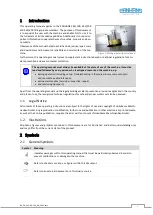
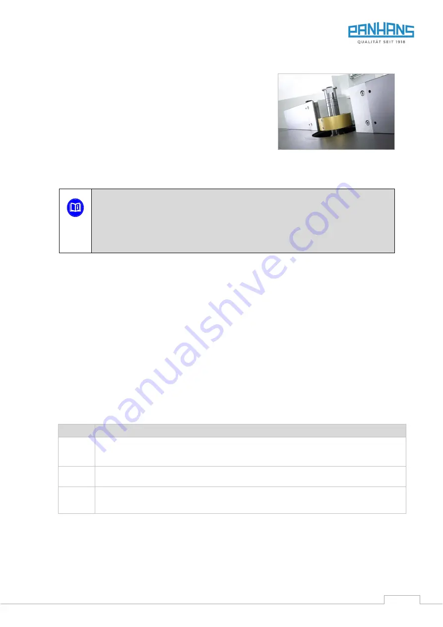
Figure 1: Milling arbor with cutter head
Furthermore, this operating manual serves to supplement instructions based on national regulations for acci-
dent prevention and environmental protection.
This operating manual must always be available at the place of use of the machine. It must be
read and followed by every person who is assigned to work on the machine, e.g.
•
during operation, including set-up, troubleshooting in the work process, removal of pro-
duction waste and maintenance,
•
during maintenance (servicing, inspection, repair)
•
and/or during transport.)
Apart from the operating manual and the legally binding accident prevention provisions applicable in the country
and place of use, the recognized technical regulations for safe and proper work must also be observed.
1.1
Legal Notice
All contents of these operating instructions are subject to the rights of use and copyright of Hokubema Maschi-
nenbau GmbH. Any reproduction, modification, further use and publication in other electronic or printed media,
as well as their online publication, requires the prior written consent of Hokubema Maschinenbau GmbH.
1.2
Illustrations
All photos, figures and graphics contained in this document are for illustration and better understanding only
and may differ from the current state of the product.
2
Symbols
2.1
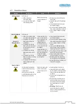
General Symbols
Symbol Meaning
Indicates passages within this operating manual that must be particularly observed in order to
prevent malfunctions or damage to the machine.
Refers to chapters, sections, or figures within this document.
Refers to an external document or a third-party source.