


BA_PH_245-100-300_EN_06-22.docx
45
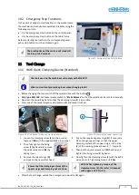
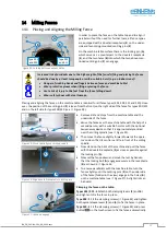
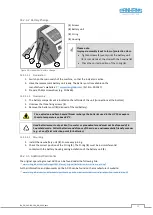
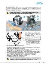
Lifting off and removing the fence
•
Remove clamping levers (
3
) and (
6
) by unscrewing them, lift off the fence and remove it.
Due to the heavy weight of the fence, this operation should be carried out by 2 persons or with a suitable hoist.
Increased risk of accidents due to the high weight of the fence! Lifting and placing the fence
should be done by at least two people or with a suitable hoist (e.g. an indoor crane)!
•
Danger of crushing hands and fingers between fence and machine table!
•
Wear protective gloves when lifting or placing the fence.
•
Acute risk of injury to the feet from the fence falling down!
•
Wear safety shoes with steel toecaps.
Lifting off with Swivel-away Device (Option)
•
Remove the clamping levers (
3
) and (
6
) by unscrewing them and swivel the fence away.
•
When using a swivel-away device, follow the instructions on the touchscreen of the control unit.
For further information see section
16.3. The detailed procedure is described in the separately enclosed op-
erating manual
BA_PH_UT300_EN
(refer to chapter “
Fence Positioning
” / section “
Swivel-away Devices
”).
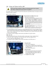
14.2.5
Fence Type 320
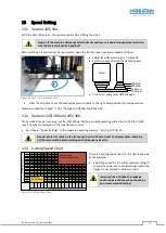
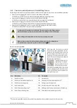
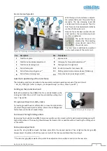
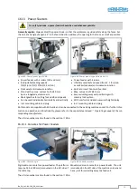
Figure 37: Operating elements Fence Type 320
With the type 320, the total and par-
tial fence are adjusted completely
automatically and clamped electro-
mechanically.
To lift off, two screws must be loos-
ened and removed manually.
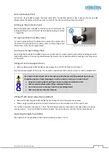
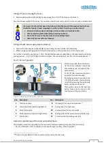
Both target positions are set via the
UT 300 touchscreen. The positioning
is started by pressing the positioning
button on the control panel.
The position values for the total and
partial fence) can be read on the
touchscreen of the control unit.
Pos. Description
Pos. Description
1
Total fence plate
8
Clamping for fence plate adjustment
2
Total adjustment (positioning button)
9
Sliding covers for high tools
4
Partial fence plate
10
Knurled screws for tool covers (
9
)
5
Partial adjustment (positioning button)
11
Milling protection & pressure device (folded up)
7
Splinter tabs
12
Protective hood (unlocking rear left)
Automatic positioning of the total and partial fence
The detailed procedure is described in the separately enclosed operating manual of the control unit
BA_PH_UT300_EN
(refer to chapter „
Fence positioning
“ / section „
Fence Type 320
“).
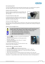
14
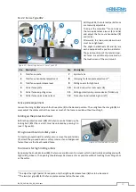
The two star grips (
8
) for the fence plates are located on the rear side.
7
10
9
4
1
8
5
UT 300
2
11
12