


CABINET SENSOR HARDWARE INSTALLATION
MANUAL
53
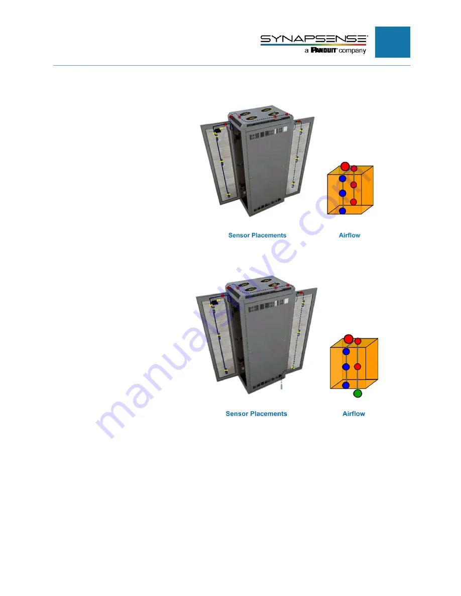
Top (Chimney)/Rear Exhaust
This diagram depicts the
installation of cabinet
sensor kits on server
cabinets with top (chimney)
and rear exhaust (airflow
enters the front of the
cabinet and exits out the
top and rear of the
cabinet).
Top (Chimney)/Rear Exhaust with Subfloor
This diagram depicts the
installation of cabinet
sensor kits on server
cabinets with top (chimney)
and rear exhaust with
subfloor (airflow enters the
front of the cabinet and
exits out the top and rear of
the cabinet).


