background image

AT-HDR-SW-51

25

Device Operation

HDCP Content

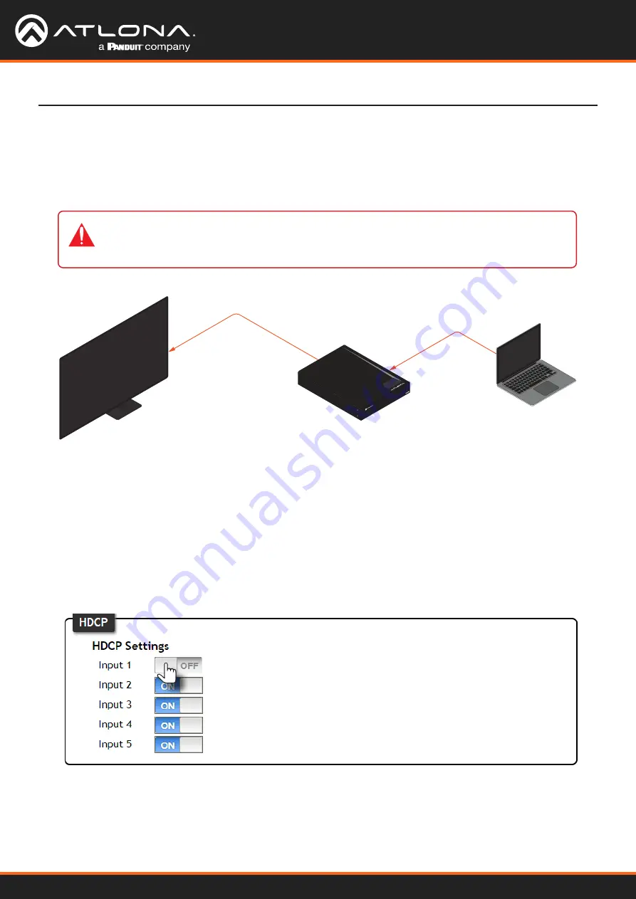
Transmitting HDCP content to a display that is not HDCP compliant can result in “snow”, image flickering, or no 

picture.  In the illustration below, a laptop source is connected to the AT-HDR-SW-51, which is connected to a 

display that is not HDCP compliant.

By default, the laptop may transmit HDCP content.  However, when connected to a display that does not support 

HDCP, the laptop must be instructed to send non-HDCP content in order for the content to be displayed.

1.  Log in to the web server.

2.  Click 

A/V Settings

 in the menu bar.

3.  Locate the 

HDCP

 section.

4.  Click the toggle switch next to the desired input.  In this example, clicking the 

Input 1

 toggle switch and setting it 

to the 

OFF

 position will instruct the source device to send non-HDCP content, if possible.


AT-HDR-SW-51

HDMI

HDMI

Non-Compliant HDCP Display

Laptop

AT-HDR-SW-51

POWER

INPUT

HDMI 1

HDMI 2

HDMI 3

HDMI 4

HDMI 5

IMPORTANT:  

Not all source devices are capable of transmitting non-HDCP content.


For example, Sony PlayStation

®

 gaming consoles and Mac

®

 computers always transmit HDCP-

encrypted content.

 If the display is unable to receive HDCP content, then a “black screen” with no image will be displayed.

Содержание ATLONA AT-HDR-SW-51

Страница 1: ...AtlonaManuals Switchers AT HDR SW 51 Five Input HDMI Switcher 4K HDR...

Страница 2: ...AT HDR SW 51 2 Version Release Date Notes 3 Jan 2024 Updated warranty information Version Information...

Страница 3: ...ose CA 95134 United States Office 1 408 962 0515 Sales and Customer Service Hours Monday Friday 6 00 a m 4 30 p m PST https atlona com International Headquarters Atlona International AG To distrasse 1...

Страница 4: ...ing two conditions 1 this device may not cause harmful interference and 2 this device must accept any interference received including interference that may cause undesired operation This equipment has...

Страница 5: ...the Web Server 18 Using the Front Panel 18 Auto Switching 19 Enabling Disabling Auto Switching 19 Scaler Pass Through 20 Notes on Scaling 21 Audio Management 22 HDMI Audio Muting 22 Analog Audio Outpu...

Страница 6: ...0 Login page 41 Info page 42 A V Settings page 43 RS 232 page 45 EDID page 46 Config page 47 System page 48 Appendix 50 Updating the Firmware 50 Using the Web Server 50 Using USB 51 Mounting Instructi...

Страница 7: ...MI switcher for high dynamic range HDR formats Part of the comprehensive family of Atlona 4K HDR integration products it features five HDMI inputs and an HDMI output The HDR SW 51 is HDCP 2 2 complian...

Страница 8: ...put LED Indicators These LED indicators display which input is routed to the HDMI OUT port A solid blue indicator represents the active input being used 2 POWER Press this button to toggle between on...

Страница 9: ...4 HDMI OUT Connect an HDMI cable from each of these ports to an HDMI display 5 FW Connect a USB to mini USB cable to this port from a computer for firmware updates 6 LAN Connect an Ethernet cable fro...

Страница 10: ...t to the Local Area Network LAN This step will be required in order to access the built in web server 4 Connect two RCA type cables from these ports to an analog audio output device 5 Connect an RCA t...

Страница 11: ...AT GAIN 60 Ceiling Speakers A u d i o A u d i o Gen eric SPEAKER SYSTEMS SPEAKER SYSTEMS Gen eric SPEAKER SYSTEMS SPEAKER SYSTEMS Gen eric SPEAKER SYSTEMS SPEAKER SYSTEMS Gen eric SPEAKER SYSTEMS SPE...

Страница 12: ...c IP mode the AT HDR SW 51 will retain the last assigned IP address until it is changed manually static IP mode or assigned a new IP address by the DHCP server 1 Make sure the AT HDR SW 51 is powered...

Страница 13: ...tation for more information Setting the IP Address Using Commands The IP mode of the AT HDR SW 51 can also be set using the built in web server In order to access the web server the IP address of the...

Страница 14: ...ter then do the following 1 Click Start Settings Control Panel Network and Sharing Center 2 Click Change adapter settings 3 Right click on the adapter that is used to establish a wired connection to t...

Страница 15: ...e A V muting is disabled Solid red Unit is powered and in standby mode In this mode A V will be muted Press the POWER button to place the unit in normal operating mode Off Unit is not powered Check th...

Страница 16: ...the built in web server can be accessed a username and password must be created 3 Enter the desired username in the Username field In the example above the username admin is used 4 Enter the desired p...

Страница 17: ...owser and enter the IP address of the AT HDR SW 51 in the address bar 2 Enter the correct username and password in the respective fields 3 Click the Submit button Logging in after Registration 4 The I...

Страница 18: ...V Settings in the menu bar 3 Click the Input Selection drop down list and select the desired input 1 Press and release the INPUT button on the front panel 2 Each time the INPUT button is pressed the A...

Страница 19: ...red click this toggle switch to the OFF position If the previously active input is no longer available then the AT HDR SW 51 will fallback to any available input The AT HDR SW 51 provides Auto Switchi...

Страница 20: ...to Notes on Scaling page 21 for more information 1 Log in to the web server 2 Click A V Settings in the menu bar 3 Click the Scaler HDMI Output 1 toggle switch to the ON position 4 The following messa...

Страница 21: ...lows Input Output 4K 24 Hz 1080p 24 Hz 4K 30 Hz 1080p 30 Hz 4K 60 Hz 4 2 0 1080p 60 Hz YUV RGB 4 4 4 HDR Dolby Vision HLG formats cannot be downscaled to 1080p The internal scaler will be bypassed if...

Страница 22: ...toggle switch to the OFF position To re enable the audio for the output set the toggle switch to the ON position The AT HDR SW 51 provides independent audio muting Audio muting can be controlled on t...

Страница 23: ...e switch to the OFF position Device Operation Analog Audio Output IMPORTANT The AT HDR SW 51 will only de embed two channel LPCM audio In addition video must accompany the audio at all times This prod...

Страница 24: ...Muting 1 Log in to the web server 2 Click A V Settings in the menu bar 3 Locate the Audio section 4 Click the S PDIF Output toggle switch to the OFF position To re enable the audio on the S PDIF OUT...

Страница 25: ...Log in to the web server 2 Click A V Settings in the menu bar 3 Locate the HDCP section 4 Click the toggle switch next to the desired input In this example clicking the Input 1 toggle switch and sett...

Страница 26: ...L R DIGIT AL COAX OUT AUDIO OUT AUDIO IN ETHE RNET 2 3 4 VIDEO OUT 48V DC FACT ORY RESET Control System AT HDR SW 51 AT H DR S W 5 1 POW ER INPU T HDM I 1 HDM I 2 HDM I 3 HDM I 4 HDM I 5 3 Click RS 2...

Страница 27: ...toring EDID Data By default the AT HDR SW 51 will read the EDID from the display device The term downstream is used to describe any device that receives a signal from another device For example if a B...

Страница 28: ...IMPORTANT If problems are encountered when using an EDID preset it is recommended that the input be set to Connected Display Not all displays will support all video and audio formats in a given EDID...

Страница 29: ...DID Data 1 Connect an HDMI cable from the HDMI OUT port on the AT HDR SW 51 to the HDMI input on the display containing the EDID to be stored 2 Log in to the web server 3 Click EDID in the menu bar 4...

Страница 30: ...AT HDR SW 51 30 Device Operation 6 Click the Save button next to the drop down list for the memory location 7 The saved EDID will appear next to the memory location as shown below Saved EDID...

Страница 31: ...ppears as an available EDID preset for each available input on the AT HDR SW 51 Device Operation Saved EDID NOTE Once an EDID is written to a memory location it can be overwritten with a different EDI...

Страница 32: ...ck the Old Password field and enter the current password 5 Enter the new username in the New Username field 6 Enter the new password in the New Password field 7 Retype the new password in the Confirm...

Страница 33: ...e assigned an IP address on the network and no further network configuration is required However if the AT HDR SW 51 is unable to detect a DHCP server within 15 seconds then the unit will use a self a...

Страница 34: ...pectively 7 Click the Save button to commit changes Changes will take effect immediately Changing the Telnet Port Typically the Telnet service is assigned to TCP port 23 This is the default setting fo...

Страница 35: ...0 4 Click Save to commit changes Telnet Login Mode Telnet Timeout When a Telnet session is requested the AT HDR SW 51 provides the option to prompt for user credentials or bypass authentication before...

Страница 36: ...eedback from the commands or any system changes Read queries such as the IPCFG and Type commands are not announced and will only return information to the requester 4 Click Save to commit changes 1 Lo...

Страница 37: ...This may be desirable if for example the AT HDR SW 51 is installed in a rack environment By default the front panel buttons are unlocked 1 Log in to the web server 2 Click System in the menu bar 3 Cl...

Страница 38: ...1 Log in to the web server 2 Click System in the menu bar 3 Click the Factory Default button 4 The following message will be displayed at the top of the screen Click OK to continue with the factory de...

Страница 39: ...uttons once the front panel LED indicators turn on After two seconds the front panel LED indicators will turn off Using the Front Panel Device Operation L R S PDIF 1 2 3 4 5 HDMI IN HDMI OUT LAN FW DC...

Страница 40: ...a built in web server Atlona recommends that the web server be used to set up the AT HDR SW 51 as it provides intuitive management of all features Refer to Logging in after Registration page 17 for m...

Страница 41: ...AT HDR SW 51 41 Configuration and Management Interfaces Login page Username Enter the username in this field Password Enter the password in this field Submit Click this button to log in...

Страница 42: ...amount of time elapsed since the unit was powered Configuration and Management Interfaces Info page System Info Video Info Displays signal information for the HDMI output Active Input The input signa...

Страница 43: ...as the active input Input 2 Sets HDMI IN 2 as the active input Input 3 Sets HDMI IN 3 as the active input Input 4 Sets HDMI IN 4 as the active input Input 5 Sets HDMI IN 5 as the active input Video A...

Страница 44: ...evices will send HDCP content if an HDCP compliant display sink is detected However there may be applications where sending HDCP content is not desired Setting the port to the OFF position will instru...

Страница 45: ...a bit Sets the number of data bits used to represent each character of data The following options are available 7 or 8 Parity Sets the parity bit which can be included with each character to detect er...

Страница 46: ...o select the desired EDID to be used for each input The following EDID presets are available When selecting an EDID make sure that the display sink device is capable of supporting the resolution timin...

Страница 47: ...sword in this field New Username Enter the new username in this field New Password Enter the new password in this field Confirm New Password Verify the new password by retyping it in this field Save C...

Страница 48: ...of a Telnet session OFF No username and password is required for Telnet sessions IP Enter the IP address of the AT HDR SW 51 in this field This field will only be available if IP Mode is set to STATIC...

Страница 49: ...closed If this field is set to 0 then the timeout interval is infinite Click the Save button to commit changes Broadcast This option determines whether or not systems changes are announced over TCP IP...

Страница 50: ...from the computer containing the firmware to the same network where the AT HDR SW 51 is connected 2 Log in to the web server and go to the System page page 48 Appendix 3 Click the Choose File button u...

Страница 51: ...R SW 51 2 Connect the USB A to mini USB cable between the computer and the FW port on the AT HDR SW 51 3 Press and hold down the INPUT button on the front panel while connecting the power supply to th...

Страница 52: ...screws on the sides of the unit to attach the mounting brackets 1 Attach the included small rack ear to one side of the AT HDR SW 51 using the included screws 2 Attach the included longer rack ear to...

Страница 53: ...P O W E R IN P U T H D M I 1 H D M I 2 H D M I 3 H D M I 4 H D M I 5 A T H D R S W 5 1 P O W E R IN P U T PWR VOL LEVEL AUDIO AMPLIFIER FW SIGNAL ANALOG IN NET AUDIO DEVICE ID GAINTM H D M I 1 H D M I...

Страница 54: ...nit using the circular holes on each mounting plate If using a drywall surface a 6 drywall screw is recommended Mounting screws are not included PWR VOL LEVEL AUDIO AMPLIFIER FW SIGNAL ANALO G IN NET...

Страница 55: ...bsampling 4 4 4 4 2 2 4 2 0 Color Depth 8 bit 10 bit 12 bit HDR HDR10 Hybrid Log Gamma HLG and Dolby Vision 60 Hz Audio HDMI Pass Through Formats LPCM 2 0 LPCM 5 1 LPCM 7 1 Dolby Digital Dolby Digital...

Страница 56: ...4 to 140 20 to 60 Operating Humidity RH 20 to 90 non condensing Power Consumption 13 53 W BTU h 46 1 External Power Supply 100 240 V AC 50 60 Hz Output 5 V 4 A DC RS 232 Port 1 x 3 pin captive screw U...

Страница 57: ...AT HDR SW 51 57 Appendix Compliance NDAA 889 Yes TAA Yes Warranty Device To view the product warranty use the following link https atlona com warranty...

Страница 58: ...US International atlona com 408 962 0515 41 43 508 4321 35293 R3...

Отзывы: