background image

27

26

USER MANUAL

PANDORA DXL 1840L CAR SERVICE-SECURITY SYSTEM

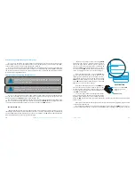
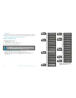
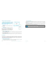
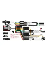
WIRING DESCRIPTION

Х 5 socket (main socket):

•  Wire «1» (White) (Tachometer input) 

— analog input of the tachometer signal, it connects to 

the tachometer wire or to the signal wire of a nozzle, which provide stable pulses of any polarity cor-

responding to the RPM.

•  Wire«2» (Red-black) (CH5) 

— Factory setting is ‘Beeper’. A negative output of additional chan-

nel with maximum load current 200mA. This output is multipurpose, it can operate in accordance with 

selected logic.

•  Wire«3» (Orange-white) (CAN1-High)  

— It connects to appropriate CAN-High wire of the car.

•  Wire«4» (Yellow-white) (CAN2-High)  

— It connects to appropriate CAN2-High wire of the car.

•  Wire«5» (Gray) (СН1/INP1) 

— Factory setting is ‘Door trigger. This wire connects to a wire that 

becomes grounded when the door opens. This wire is multipurpose, it can operate as input and as 

output in accordance with selected logic.

•  Wire«6» (Green) (СН4/INP4) 

— Factory setting is ‘Control turn indicators’. This wire connects to 

the hazard flashers button. A negative output of additional channel with maximum load current 200mA. 

This wire is multipurpose, it can operate as input and as output in accordance with selected logic.

•  Wire«7» (White-Blue) (INP5) 

— Factory setting is ‘Brake pedal’. This wire connects to the brake pedal 

trigger where 12V voltage appears when the pedal is pressed (stop lights wire). Brake pedal signal is one of 

the system’s security zones. This input is multipurpose, it can operate in accordance with selected logic.

•  Wire«8» (Black) (Ground) 

— It should be connected to the car body in a grounding spot. This 

wire should be connected FIRST during installation.


•  Wire«9» (Blue) (CH2/INP6) 

—  Factory setting is free output. A negative output of additional 

channel with maximum load current 200mA. This wire is multipurpose, it can operate as input and as 

output in accordance with selected logic.

•  Wire«10» (Brown-White) (INP3) 

— Factory setting is ‘Front hood and trunk trigger’. This wire 

connects to appropriate wire that becomes grounded when the front hood opens. This input is multi-

purpose, it can operate in accordance with selected logic.

•  Wire«11» (Orange-black) (CAN1-Low)   

— It connects to appropriate CAN-Low wire of the car.

•  Wire«12» (Yellow-black) (CAN2-Low) 

— It connects to appropriate CAN2-Low wire of the car.

•  Wire«13» (Blue-Black) (CH3) 

—Factory setting is ‘Blocking N.O.’. This output is used to control 

blocking relay with a normally open logic (it becomes grounded when switching on the ignition and 

security system is not armed). A negative output of additional channel with maximum load current 

200mA. This output is multipurpose, it can operate in accordance with selected logic.

•  Wire«14» (Yellow) (INP2) 

— Factory setting is ‘Ignition’. This wire connects to ignition switch or to 

appropriate wire where 12V voltage appears when ignition is switched on. This input is multipurpose, it 

can operate in accordance with selected logic.

•  Wire«15» (Purple) (Siren) 

— It connects to siren control wire (+) (maximum load current is 2A).

•  Wire«16» (Red) (Power 12V) 

— It should be connected to reliable conductor with con-

stant voltage of 12V.

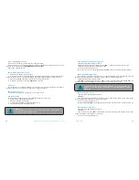
Х 6 Socket (Relay module):

•  Wire«1» (Blue) (CH6) 

— Factory setting is ‘Blocking N.O.’. This output is used to control blocking 

relay with a normally open logic (it becomes grounded when switching on the ignition and security 

system is not armed). A negative output of additional channel with maximum load current 200mA. This 

output is multipurpose, it can operate in accordance with selected logic


•  Wire«2» (Orange) (CH7) 

— Factory setting is ‘ACC’. The channel is used to control accessories. If 

‘Car with START/STOP button’ setting is enabled, the channel will control brake pedal during remote or 

automatic engine start. A negative output of additional channel with maximum load current 200mA. 

This output is multipurpose, it can operate in accordance with selected logic.

•  Wire«3» (Brown) (CH8) 

— Factory setting is ‘Ignition’. This output is used to switch on ignition. 

It allows implementing automatic engine start, turbo timer, ignition support and connecting to igni-

tion in series (incut). If ‘Car with START/STOP button’ setting is enabled, the channel will operate in im-

pulse mode to control the button. A negative output of additional channel with maximum load current 

200mA. This output is multipurpose, it can operate in accordance with selected logic.

•  Wire«4» (Green) (CH9)

— Factory setting is ‘Bypass’. Output activates during remote or automatic 

Содержание DXL 1840L

Страница 1: ...in Fed eration and nearest states We are happy to provide any support we can feel free to use our online support This device has limited external factors resistance It should not be subjected to water...

Страница 2: ...mode 6 Arming disarming in Slave mode 6 Immobilizer mode 7 Anti Hi Jack 1 mode 7 Anti Hi Jack 2 mode 8 Code immobilizer using original car controls 8 Maintenance mode 8 Replacing immobilizer tag batte...

Страница 3: ...commands Individual 128 bit encryption key Built in LED indicator Built in button to control over security modes Built in integral accelerometer Car security zones Pandora DXL 1840L service security...

Страница 4: ...disarming using radio tag To arm disarm the system RF tag should be in the Bluetooth coverage area The system produces a protected AES 128 encryption interac tive high speed exchange of authorization...

Страница 5: ...anic You can enable disable this mode using a radio tag mobile phone or immobilizer button if the Code immobilizer function is implemented Enable Disable the maintenance mode using a radio tag To enab...

Страница 6: ...Press the button a number of times equals to the second digit Pauses between presses should not exceed 1 second Each pressing will be confirmed with an orange LED indicator flash A Pause for more tha...

Страница 7: ...g menu Control over the system via a phone Call the system s phone number When it answers enter a command code DTMF commands For example To have simple access to engine start function create a new con...

Страница 8: ...all automatic engine starts or 789 to enable all automatic engine starts 3 The system will confirm the command execution To end session hung up the phone Automatics starts can be enabled again by dia...

Страница 9: ...he shock sensor sensitivity Settings of the alarm level of the shock sensor sensitivity Settings of the motion sensor sensitivity 1 1 2 2 3 3 4 4 Settings of the tilt sensor sensitivity Settings of th...

Страница 10: ...vent history holds more than 100 different types of events that can happen to the system Every event is saved with date time coordinates additional GPS GLONASS receiver NAV 035 BT is required and stat...

Страница 11: ...ates Exterior temperature 13 5V Security mode icon 08 24 18 of January Engine start by command via online service 14 3V 28O C 32O C 82O C Fuel 30 FUEL F FUEL Event history Arming 165 Fleet St London E...

Страница 12: ...can be performed via twisting together or via lead tin soldering followed by isolation of a switching place When wiring pay attention to sections and materials of switched conductors if they are diff...

Страница 13: ...ut to beeper CH1 INP1 Doors triggers CH4 INP4 To turn signals to original wiring INP5 Brake pedal input fuel level control INP3 Front hood Trunk trigger H3 OUT NO Blocking INP2 To ignition lock CH11 S...

Страница 14: ...selected logic Wire 11 Orange black CAN1 Low It connects to appropriate CAN Low wire of the car Wire 12 Yellow black CAN2 Low It connects to appropriate CAN2 Low wire of the car Wire 13 Blue Black CH...

Страница 15: ...Then you can enter the next digit Enter the third digit of the code using VALET button Press the button a number of times equals to the third digit Pauses between presses should not exceed 1 second Ea...

Страница 16: ...Programming bypass of original immobilizer Level 18 Pairing and unpairing mobile device Level 19 20 Updating radio relays 1 2 firmware BTR 101 Level 21 Updating Bluetooth engine compartment module fi...

Страница 17: ...ng of the idle speed will be confirmed with the series of red and green flashes of LED indicator The system will exit programming menu and reboot after saving the idle speed Level 4 Resetting to facto...

Страница 18: ...LED indicator will confirm input with orange flashes If there are no orange flashes when any button is pressed then this button is not recognized by the system select a different button Repeat the pr...

Страница 19: ...e only after unpairing procedure Pairing mobile device LED indicator will light green after entering the level Open Pandora Online mobile application go to Bluetooth Control Not specified menu Bluetoo...

Страница 20: ...a 2 4 GHz 12V WARINGI DO NOT PLACE RADIO RELAYS DIRECTLY ON THE ENGINE Radio tag BT 760 Radio module of engine compartment RHM 03 BT Radio module of engine compartment RHM 03 BT This module is designe...

Страница 21: ...d The system is preparing for automatic arming Orange flash Confirms VALET button press Green flashes Confirms a number of recorded remotes when switching on ignition Red flash Confirms a recorded mob...

Страница 22: ...rage or transportation conditions were not met if there is mechanical damage of the external parts of the system after it is sold This includes fire damage consequential damage in case of car accident...

Страница 23: ...____________________________________________________________ ______________________________________________________________________________ Signature_____________________ _____________________________...

Страница 24: ...47 46 USER MANUAL PANDORA DXL 1840L CAR SERVICE SECURITY SYSTEM...

Страница 25: ...48 PANDORA DXL 1840L CAR SERVICE SECURITY SYSTEM...

Отзывы: