background image

13

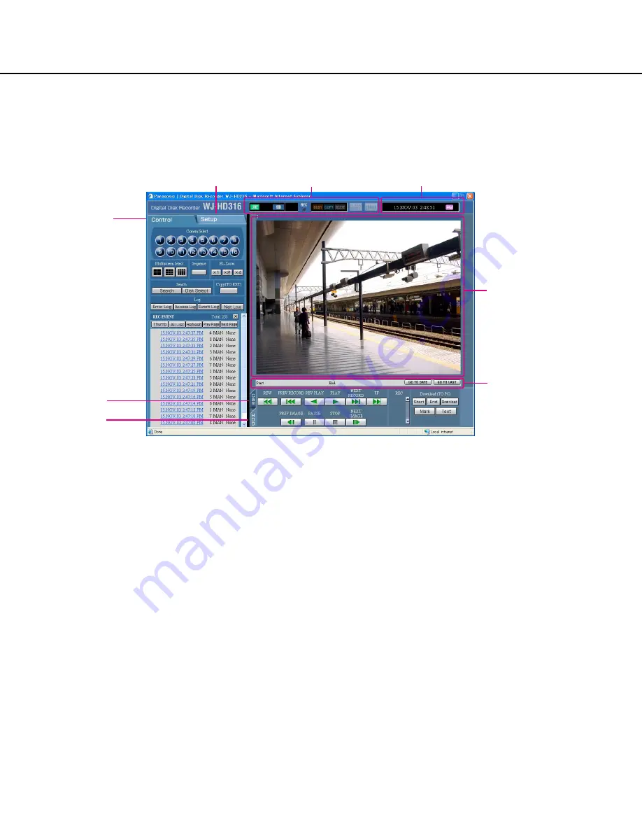
About the operation window

Top page

[Control] tab (page 14)

The switcher functions such as switching camera chan-
nels or displaying sequentially, are operable on this
page.  Search results or log information will also be dis-
played on this page.

[Setup] tab (page 15)

Operations for setup of this unit can be performed on
this page.

Status display area (page 16)

Current status such as playback status or recording sta-
tus will be displayed.

Current time/play time displayed area

Current time and play time will be displayed during play-
back.

Image display area

Recorded images and live images will be displayed. The
setup menu will be displayed while setting up.

Playback point operation area (page 17)

It is possible to mark playback points or skip to the lat-
est recorded image.

[HDD] tab (page 17)

Operation for recorded images such as playback or
downloading (saving) recorded images can be per-
formed on this page.

[Cam] tab (page 18)

Controlling cameras by zooming, focusing and auto
panning can be performed on this page.

[Control] tab

[Setup] tab

Status display area

Current time/play time displayed area

Image display area

Playback point
operation area

[HDD] tab

[Cam] tab

Содержание WJHD309 - DIGITAL DISK RECORDER

Страница 1: ...SUSPEND OPERATE Digital Disk Recorder WJ HD 316 MONITOR1 MONITOR2 SHIFT DISKSELECT EL ZOOM COPY TEXT MARK PAN TILT ZOOM FOCUS IRIS LISTED BUSY A B REPEAT PAN TILT SLOW SETUP ESC SEARCH REV FWD SET GO...

Страница 2: ...2...

Страница 3: ...w to display the operation window 11 About the operation window 13 Setup 19 SETUP MENU chart 19 Basic operation with the Setup Tab 22 Settings for maintenance Maintenance 24 Functions for recording Re...

Страница 4: ...operating this unit if their IP addresses are not registered About these operating instructions There are 3 operating instructions for WJ HD316 WJ HD309 as follows Operating Instructions book Network...

Страница 5: ...nd installed automatically when accessing the unit using a browser If the plug in software has not been down loaded installed correctly install it from the provided CD ROM Refer to readme txt on the p...

Страница 6: ...GE 10 100BASE T RS485 CAMERA DATA AC IN SIGNAL GND 1 4 2 This unit LAN cable Not provided 10BASE T 100BASE Tx Category 5 Cross IP Address 192 168 0 250 Subnet mask 255 255 255 0 IP Address 192 168 0 x...

Страница 7: ...form the network settings of this unit and the PC Performing network settings of this unit Use the buttons on the front panel of this unit to conform to the network settings to the network environment...

Страница 8: ...ed Step 4 Double click Local Area Connection 8 Screenshot 2 The control panel will be displayed Step 2 Click the Network and Internet Connections icon Screenshot 3 The Network and Internet Connections...

Страница 9: ...Properties window of Local Area Connection will be displayed Step 5 Click Properties Screenshot 7 The Properties window of Internet Protocol TCP IP will be displayed Step 7 Click Use the following IP...

Страница 10: ...ons can better enhance the network security Connection example WAN Router Router Global IP Address IP Address 192 168 1 100 Subnet Mask 255 255 255 0 Default Gateway 192 168 1 1 IP Address 192 168 0 2...

Страница 11: ...of this unit It is impossible to access this unit from a PC without a registered IP address when ON is selected for Host Authentication on the System menu Refer to a system administrator for further i...

Страница 12: ...a system administrator for the set user name and password Refer to page 86 for the descriptions of how to regis ter users The default user name and password are as follows User Name ADMIN Password 123...

Страница 13: ...ent time and play time will be displayed during play back Image display area Recorded images and live images will be displayed The setup menu will be displayed while setting up Playback point operatio...

Страница 14: ...rch button The Search Select pop up window will be displayed Use this button to search the recorded images and play them Refer to the Network Operating Instructions PDF Search results will be displaye...

Страница 15: ...hedule performs recording event action by designating time and a day of the week will be displayed Refer to page 42 for further information about this menu Switcher button The menu for the image switc...

Страница 16: ...vent list STEP1 STEP7 Indicates the playback speed STEP1 Normal playback speed STEP2 Approx 4x playback speed STEP3 Approx 8x playback speed STEP4 Approx 16x playback speed STEP5 Approx 32x playback s...

Страница 17: ...approx 96x PREV RECORD button Skips to the previous recorded image and plays it REV PLAY button Reverse playback of a recorded image will be per formed PLAY button Playback of a recorded image will be...

Страница 18: ...clicking this button during playback When marked playback after searching for the marked point is be available Refer to the Network Operating Instructions PDF Text button The attached text information...

Страница 19: ...recording such as recording time and recording rate can be performed on this menu Event Event Setup Settings for event action can be performed with this menu VMD Setup The motion detection area sensit...

Страница 20: ...splay Monitor 2 Perform the display settings for the monitor 2 such as task bar style time display position and camera title display Comm Camera Control Communication method to control cameras for eac...

Страница 21: ...at an event occurrence System Basic Setup Settings for basic operations of this unit can be performed Time Date Setup Settings for the current time and for displaying time date can be performed User R...

Страница 22: ...peration with the Setup Tab Screenshot 1 Start operation after the top menu is displayed STEP 1 Click the Setup tab Screenshot 2 The Setup tab will be displayed STEP 2 Click a button on the Setup tab...

Страница 23: ...he settings for each item Click the SET button after completing the settings When the CLEAR button is clicked the content of the setting will be cleared STEP 5 To complete the setting menu click the R...

Страница 24: ...FINE High quality FQA FQB NORMAL Standard NQA NQB EXTENDED Low quality EXA EXB 24 Settings for maintenance Maintenance Settings for the hard disk can be performed Checking the recording rate or image...

Страница 25: ...the settings Confirmation of available hard disk space Disk Information Available disk space for the following disks will be displayed built in hard disk normal recording area event record ing area an...

Страница 26: ...Setup tab page 15 Step 1 Click Version information 26 Confirmation of version information Version Information Version information of the software and hardware will be displayed Screenshot 2 The Versio...

Страница 27: ...ill be canceled when the available disk space has run out even though CONTINUE is selected for Disk End Mode 27 Screenshot 1 Start operation after the submenu of the maintenance menu is displayed by c...

Страница 28: ...issued Screenshot 1 Start operation after the submenu of the maintenance menu is displayed by clicking the Maintenance button in the Setup tab page 15 Step 1 Click Disk Capacity Screenshot 2 The Disk...

Страница 29: ...when entering the time and date Manual Delete for Event Recording Area By setting the time and date images in the event recording area of the hard disk that were recorded up until a day before the se...

Страница 30: ...ayed Step 2 Perform the settings for each item Refer to page 31 for further information about the set tings for each item Step 3 Click the SET button after completing the settings 30 Functions for rec...

Страница 31: ...all camera channels when displaying images in the sequential display mode or live image even though MON2 is selected Colour Mode Set the colour mode for recording COLOUR FINE Records images in high re...

Страница 32: ...m manual recording schedule recording with lower priorities than the priority of event recording Audio Allocation Allocates audio from the audio input connectors 1 4 on the rear panel of the unit to c...

Страница 33: ...EC Perform the settings for emergency recording such as recording time or recording rate Refer to the provided operat ing instructions for further information about emergency recording Screenshot 2 Th...

Страница 34: ...ed for a specified camera channel images from a camera channel set to OFF will not be recorded OFF 1 7 ips 2 5 ips 4 2 ips 5 ips 6 3 ips 8 3 ips 12 5 ips 25 ips 50 ips 100 ips Important The total reco...

Страница 35: ...tant Alarm output duration can not be set for video loss Signals will be supplied continuously from the camera error output terminal pin no 17 of the ALARM CONTROL connector on the rear panel during t...

Страница 36: ...owing are available for alarm output duration 1 s 30 s in 1 second intervals 40 s 50 s 1 m 2 m 3 m 4 m 5 m EXT Alarm output will continue until the ALARM RESET button on the front panel of the unit is...

Страница 37: ...espective SETUP button for the desired camera channel to be set Important When OFF is selected for a camera channel the motion detection function will be disabled for the camera channel Settings for t...

Страница 38: ...tion in a detection area is available by setting the detection mode Refer to page 39 for further information about each recording mode ANY AREA An event action will be performed according to the setti...

Страница 39: ...le Motion is detected in area B within 10 seconds after being detected in area A Motion is detected in area C within 20 seconds after being detected in area B Motion is detected in area D within 10 se...

Страница 40: ...ension Alarm Setup Perform the settings for the alarm displaying duration The alarm display will automatically disappear when the dis playing duration has passed Alarm Auto Reset The following will be...

Страница 41: ...tup menu will be displayed Step 2 Select polarities for each terminal by clicking the i button N O Signals will be supplied when open circuited Normally Open N C Signals will be supplied when short ci...

Страница 42: ...ssible to create special days apart from the normal schedule and a recording program of another day of the week can be switched to a special day s program automatically Flowchart how to create a sched...

Страница 43: ...program Screenshot 3 The Schedule Recording Program menu will be dis played Step 3 Perform the settings for each item Refer to page 44 for further information about the set tings for each item Step 4...

Страница 44: ...less than 50 ips Manual recording 12 5 ips Schedule recording 12 5 ips Event recording 25 ips Recording Rate and Image Quality for Each Camera Channel Perform the settings for recording rate image qu...

Страница 45: ...ressed or the ALARM RESET button in the status display area is clicked Notes When performing event pre recording from a camera channel that does not have its own event pre record ing area recording ti...

Страница 46: ...detection video loss terminal com mand alarm Screenshot 1 Start operation after the submenu of the schedule menu is displayed by clicking the Schedule button in the Setup tab page 15 Step 1 Click Even...

Страница 47: ...esired event to be set Screenshot 5 The setup menu for the event action will be displayed Step 5 Perform the settings for each item Refer to page 48 for further information about the set tings for eac...

Страница 48: ...tem the auto copy function will not work even though ON is selected for this setting Select HDD COPY 1 or COPY 2 for Auto copy Images recorded by event pre recording in the pre recording area on the h...

Страница 49: ...can be created Screenshot 1 Start operation after the submenu of the schedule menu is displayed by clicking the Schedule button in the Setup tab page 15 Step 1 Click Time Table Screenshot 2 The Time T...

Страница 50: ...perating Instructions PDF for descriptions of how to operate the viewer software ERROR REPORT MAIL Select ON or OFF to determine whether or not to send an error mail when a trouble occurred Refer to p...

Страница 51: ...g programs or the event programs will be applied Recording programs will be displayed with different colours Recording program 1 event program 1 Orange Recording program 2 event program 2 Yellow Recor...

Страница 52: ...days and apply recording schedule to the specified special days Screenshot 1 Start operation after the submenu of the schedule menu is displayed by clicking the Schedule button in the Setup tab page...

Страница 53: ...onitor 1 Monitor 1 Perform the settings for the switcher function of monitor 1 Screenshot 1 Start operation after the submenu of the switcher menu is displayed by clicking the Switcher button in the S...

Страница 54: ...e sequence EXT Switches images by signals from an external device MON 2 Match with the image switching timing of the live sequence on monitor 2 Auto Skip Select ON of OFF to determine whether or not t...

Страница 55: ...nction of monitor 2 Monitor 2 Perform the setting for the switcher function of monitor 2 Screenshot 1 Start operation after the submenu of the switcher menu is displayed by clicking the Switcher butto...

Страница 56: ...r completing the settings Perform the settings to display on a PC monitor with the switcher function Network Perform the settings for the switcher function when displaying images on a monitor of a PC...

Страница 57: ...ork traffic the sequential dis play may not work exactly with the set interval time for DWELL 4 Screen Live Sequence Perform the settings for the sequential display when dis playing images with the se...

Страница 58: ...titles or the settings of the time display position Screenshot 1 Start operation after the submenu of the display menu is displayed by clicking the Display button in the Setup tab page 15 Step 1 Clic...

Страница 59: ...together the time display position will be determined on this setting Refer to page 31 for fur ther information about embedding the time display L UPPER Displays a camera title at the upper left of th...

Страница 60: ...e Setup tab page 15 Step 1 Click Monitor 1 Screenshot 2 The Monitor 1 menu will be displayed Step 2 Perform the display settings for monitor 1 Time Date Display Select ON or OFF to determine whether t...

Страница 61: ...a display mode task bar style from the follow ing Refer to the provided Operating Instructions for fur ther information about the style of screen MODE1 Select MODE1 for the display mode MODE2 Select M...

Страница 62: ...m the communication settings for each camera channel to control cameras Screenshot 1 Start operation after the submenu of the communication menu is displayed by clicking the Comm button in the Setup t...

Страница 63: ...9 CH are available for the WJ HD309 It is possible to compensate for the video signal trans mission loss from the camera when using the VIDEO IN connector 1 8 cable compensation Perform the settings f...

Страница 64: ...ation menu is displayed by clicking the Comm button in the Setup tab page 15 Step 1 Click PS Data Setup Screenshot 2 The PS Data Setup menu will be displayed Step 2 Perform the settings for each item...

Страница 65: ...not possible 8 bit Parity Select a method of error check for a transmission at communication from the following NONE No parity check EVEN Even parity ODD Odd parity Stop Bit Select a stop bit from th...

Страница 66: ...munication menu is displayed by clicking the Comm button in the Setup tab page 15 Step 1 Click RS485 Setup Screenshot 2 The RS485 Setup menu will be displayed Step 2 Perform the settings for each item...

Страница 67: ...or each camera channel Click the SET button after completing the settings and close window by clicking the button at the top right of the window PORT1 Controls from the RS485 port 1 PORT2 Controls fro...

Страница 68: ...f the communication menu is displayed by clicking the Comm button in the Setup tab page 15 Step 1 Click RS232C Setup Screenshot 2 The RS232C Setup menu will be displayed Step 2 Perform the settings fo...

Страница 69: ...on speed for data transmission with a connected device from the following 9 600 19 200 38 400 bps Data Bit Select a data length for communication from the follow ing 7 8 bit Parity Select a method of...

Страница 70: ...n after the submenu of the communication menu is displayed by clicking the Comm button in the Setup tab page 15 Step 1 Click Network Setup 1 Screenshot 2 The Network Setup 1 menu will be displayed Ste...

Страница 71: ...n the unit is accessed from a PC When ON is selected only the PC with the registered IP address can access the unit and control it via a net work It is possible to enhance the network security by sett...

Страница 72: ...peration after the submenu of the communication menu is displayed by clicking the Comm button in the Setup tab page 15 Step 1 Click Network Setup 2 Screenshot 2 The Network Setup 2 menu will be displa...

Страница 73: ...r addresses in Preliminary and Secondary For this unit enter 4 units of the decimal number 0 255 DDNS Select ON or OFF to determine whether or not to use the DDNS Dynamic Domain Name Server To select...

Страница 74: ...EM NAME Enter a system name in alphanumeric characters to manage this unit by the SNMP system for example No1 Enter up to 255 alphanumeric characters LOCATION Enter a location name location where this...

Страница 75: ...he present time accurate within 5 seconds by setting the Time Adjustment to ON Step 2 Perform the settings for the following item Time Adjustment Select ON or OFF to determine whether or not to adjust...

Страница 76: ...esignated FTP server Screenshot 1 Start operation after the submenu of the communication menu is displayed by clicking the Comm button in the Setup tab page 15 Step 1 Click Network FTP Setup Screensho...

Страница 77: ...he settings for the rules about the file name to be sent Select whether to Use the time and date as a file name or Use a number as a file name Interval Enter a transmission interval Select whether it...

Страница 78: ...or the post recorded images from the following OFF 1 s 10 s in 1 second intervals Note The following characters can be entered A B C D E F G H I J K L M N O P Q R S T U V W XY Z a b c d e f g h i j k...

Страница 79: ...Mail Setup menu will be displayed Step 2 Perform the settings for each item Refer to page 80 for further information about the set tings for each item Step 3 Click the SET button after completing the...

Страница 80: ...om sender line Enter up to 255 alphanumeric characters Entering hyphens and periods is possible POP Server address Select ON or OFF to determine whether to enable or disable the POP server authenticat...

Страница 81: ...nu will be displayed Step 2 Perform the settings for each item Refer to page 82 for further information about the set tings for each item Step 3 Click the SET button after completing the settings Perf...

Страница 82: ...o assign priorities to operate this unit in case two or more users access this unit simulta neously A priority is followed Users with higher priority can operate this unit Pre priority A user who acce...

Страница 83: ...RAM disk connected to the copy 1 port COPY 2 Images will be copied to the DVD RAM disk connected to the copy 2 port HDD Images will be copied to the copy area of the hard disk of this unit Important W...

Страница 84: ...ick Time Date Setup Screenshot 2 The Time Date Setup menu will be displayed Step 2 Perform the settings for each item Refer to page 85 for further information about the set tings for each item Step 3...

Страница 85: ...nal will be supplied from the ALARM CONTROL connector on the rear panel of the MASTER unit to the other connected devices and the other devices will adjust their clocks with ref erence to the clock of...

Страница 86: ...e SET button after completing the settings Note Repeat steps 2 and 3 to register two or more users Screenshot 1 Start operation after the submenu of the communication menu is displayed by clicking the...

Страница 87: ...HD309 Displays live images from the camera channels 9 12 on a 4 split screen When WJ HD309 is used live images from only camera chan nel 9 will be displayed on the upper left screen of a 4 split scre...

Страница 88: ...l be displayed with information of the registered user Edit user information in the same way as the user registration page 86 Click the DELETE button to delete the selected user Screenshot 1 Start ope...

Страница 89: ...er completing the settings Note Repeat steps 2 and 3 to register two or more users Screenshot 1 Start operation after the submenu of the communication menu is displayed by clicking the System button i...

Страница 90: ...screen When WJ HD309 is used live image from only the camera channel 9 will be displayed on the upper left screen of a 4 split screen QUAD13 16 only for the WJ HD316 Displays live images from the cam...

Страница 91: ...displayed with information of the registered host Corrections can be performed in the same way as registration page 89 Click the DELETE button to delete the selected host IP address Screenshot 1 Star...

Страница 92: ...fied picture above Step 2 Check the desired functions to allow to operate To not allow a user to operate certain functions do not check the respective function Refer to the next page for further infor...

Страница 93: ...splayed and you can refer to the access log Refer to page 14 Trouble Log Status The SETUP MENU is displayed and you can refer to the trouble log Refer to page 14 Alarm Reset An event action can be can...

Страница 94: ...on to call up the saved settings Screenshot 1 Start operation after the submenu of the communication menu is displayed by clicking the System button in the Setup tab page 15 Step 1 Click Save Load Sav...

Страница 95: ...when editing the contents of the mail Save the edited mail contents as the file name of almmail tmpl Step 2 Start up the FTP software and enter the IP address of the unit to connect to the unit Enter...

Страница 96: ...Dec Day when the alarm occurred 05000300 1 or 2 digit display 1 31 Time when the alarm occurred 05000400 24 hour display 15 00 00 Mail address of the sender 05000500 Host name of HD316 05000600 HD316...

Страница 97: ...nues if more disks are connected installed HDD Capacity warning 1 except FULL HDD NORMAL CAPACITY REMAINS HDD EVENT CAPACITY REMAINS indicates set value 0 FULL HDD NORMAL IS FULL HDD EVENT IS FULL HDD...

Страница 98: ...TUS The description of the capacity warning will be displayed except FULL HDD COPY CAPACITY REMAINS COPY1 CAPACITY REMAINS COPY2 CAPACITY REMAINS indicates set value 0 FULL HDD COPY IS FULL COPY1 IS F...

Страница 99: ...he Don t Use Proxy For These Addresses box is recommended 73 Aren t you accessing the wrong IP address Check the connection as follows ping IP address of this unit If there is a reply from this unit t...

Страница 100: ...oard to request images The image is not refreshed Can not close the authenti cation window displayed when displaying the basic operation window 87 Reference pages Cause solution Symptom Audio sounds f...

Страница 101: ...Matsushita Electric Industrial Co Ltd Osaka Japan http www panasonic co jp global 2004 Matsushita Electric Industrial Co Ltd All rights reserved N0104 1024 V8QB6178BN Printed in Japan...

Отзывы: