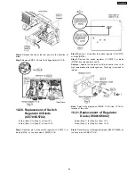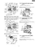
Step 8
Release the tab of the rear panel in the direction of
arrow.
Step 9
Remove SMPS, AC-Inlet & Voltage Selector P.C.B.
10.20. Replacement of Switch
Regulator IC/Diode
(IC5701/D5702)
·
Follow (Step 1) to (Step 3) of Item 10.3.
·
Follow (Step 1) to (Step 9) of Item 10.19.
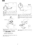
Step 1
Desolder pins of the switch reguIator IC (IC5701) or
diode (D5702) on the back side of SMPS P.C.B.
Step 2
Remove 1 screw from the switch regulator IC (IC5701)
or diode (D5702).
Step 3
Remove the switch regulator IC (IC5701) or diode
(D5702) from the heatsink unit B.
Caution :
Handle the heatsink unit B with caution due to its
high temperature after prolonged use. Touching it may lead to
injuries.
Note :
Refer to the diagrams of SMPS P.C.B. (Item 10.19) for
location of the parts.
10.21. Replacement of Regulator
Diode (D5801/D5802)
·
Follow (Step 1) to (Step 3) of Item 10.3.
·
Follow (Step 1) to (Step 9) of Item 10.19.
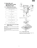
Step 1
Desolder pins of the regulator diode (D5801/ D5802) on
the back side of SMPS P.C.B.
59
SA-PT550GCP
Содержание SA-PT550GCP
Страница 3: ...3 SA PT550GCP ...
Страница 12: ...12 SA PT550GCP ...
Страница 22: ...8 New Features 8 1 About HDMI 8 1 1 What is HDMI 8 1 2 Advanced Digital Pictures 22 SA PT550GCP ...
Страница 23: ...8 1 3 Advanced Digital Sound 8 1 4 Easy to Use 8 1 5 HDMI Compatible Products 23 SA PT550GCP ...
Страница 49: ...10 2 Main Components and P C B Locations 49 SA PT550GCP ...
Страница 65: ...Step 3 Remove the middle chassis Step 4 Remove the traverse unit 65 SA PT550GCP ...
Страница 68: ...68 SA PT550GCP ...
Страница 82: ...SA PT550GCP 82 ...
Страница 92: ...92 SA PT550GCP ...
Страница 110: ...SA PT550GCP 110 ...
Страница 118: ...SA PT550GCP 118 ...
Страница 126: ...25 Exploded Views 126 SA PT550GCP ...
Страница 127: ...25 1 Cabinet Parts Location SA PT550GCP 127 ...
Страница 128: ...SA PT550GCP 128 ...
Страница 129: ...25 2 Packaging SA PT550GCP 129 ...


