20
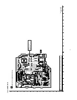
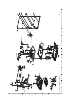
Exploded V
iew and Replacement Part
s L
ist
20
.1
.
Exploded V
iew and Mechan
ical replacement Part L
ist
20
.1
.1
.
Cab
inet Part
s Locat
ion
(USB P
.C.B.)
(REMOTE SENSOR P
.C.B.)
(P
ANEL
P
.C.B.)
(LCD P
.C.B.)
*ZJ6002
*ZJ6001
Z900
VR6002
VR6001
J
K
1111
IR6000
CN6006
CN6005
CN6001
CN6000
39
38
37
36
35
34
33
32
31
28
25
24
20
18-5
18-4
18-3
18-3
18-2
18-1
18
15
15
15
15
15
13
13
13
13
12
12
12
12
12
12
12
12
12
11
10
7
3
a
b
b
c
1
2
3
4
5
6
7
8
9
A
B
C
D
E
F
G
H
10
1
1
12
13
NOTE: " * " PART IS NOT SUPPLIED / REF IS FOR INDICATION ONLY.
SA-AKX14
CABINET DRAWINGS
98
Содержание SA-AKX14LM-K
Страница 14: ...5 General Introduction 5 1 Media Information 14 ...
Страница 15: ...6 Location of Controls and Components 6 1 Remote Control Key Button Operation 15 ...
Страница 16: ...6 2 Main Unit Key Button Operation 16 ...
Страница 17: ...7 Installation Instructions 7 1 Speaker and A C Connection 17 ...
Страница 28: ... 3 D Amp IC Operation Control 28 ...
Страница 33: ...11 2 Main Components and P C B Locations 33 ...
Страница 63: ...Step 9 Ground the 24P FFC with a short pin 63 ...
Страница 67: ...14 Simplified Block Diagram 14 1 Overall Simplified Block Diagram 67 ...
Страница 68: ...14 2 Power Block Diagram 68 ...
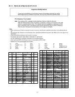
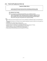
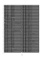
Страница 103: ...20 2 Electrical Replacement Part List 103 ...

