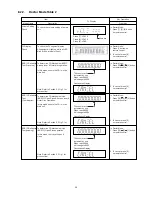
8.2.2.
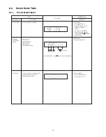
Doctor Mode Table 2
FL Display
Key Operation
Front Key
Item
Description
Mode Name
Volume Setting
Check
FL Display
Check
To check the volume setting of a main
unit.
To check the FL segment display
All segment will light up while all LED
blink at 0.5s,intervals.(if any)
In Doctor Mode:
1. Press [7], [8], [9] button
on remote control.
In Doctor mode:
1. Press [1] button on
remote control.
Press [7]: VOL50
Press [8]: VOL35
Press [9]: VOL0
Volume
In this mode, the tray will open &
close.
Note: Refer to Section 6.3 Fig 1 for
process flow.
The counter will
increment by one.
When reach 9999
will change to 0000
Cancellation Display
BRS1C Reliability
Test (Loading)
To determine CD Mechanism Unit
(BRS1C) Open/Close operation.
Note: Refer to Section 6.3 Fig 2. for
process flow.
The counter will
increment by one.
When reach 9999
will change to 0000
Cancellation Display
BRS1C Reliability
Test (Traverse)
To determine CD Mechanism BRS1C
Access Inner & Outer disc operation.
Note: Refer to Section 6.3 Fig 3. for
process flow.
The counter will
increment by one.
When reach 9999
will change to 0000
Cancellation Display
BRS1C Reliability
Test
(Combination)
In this mode,ensure the CD is in the
main unit.
To determine CD Mechanism Unit
(BRS1C) Open/Close & Access Inner &
Outer Disc Operation.
In this mode,ensure the CD is in the
main unit.
In Doctor Mode:
1. Press [10]
[2]
[1] button
on remote control.
2. To cancel, press [0]
on remote control.
In Doctor Mode:
1. Press [10]
[1]
[2] button
on remote control.
2. To cancel, press [0]
on remote control.
2. To cancel, press [0]
on remote control.
In Doctor Mode:
1. Press [10]
[1]
[5] button
on remote control.
2. To cancel, press [0]
on remote control.
20
Содержание SA-AKX14LM-K
Страница 14: ...5 General Introduction 5 1 Media Information 14 ...
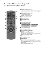
Страница 15: ...6 Location of Controls and Components 6 1 Remote Control Key Button Operation 15 ...
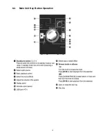
Страница 16: ...6 2 Main Unit Key Button Operation 16 ...
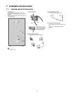
Страница 17: ...7 Installation Instructions 7 1 Speaker and A C Connection 17 ...
Страница 28: ... 3 D Amp IC Operation Control 28 ...
Страница 33: ...11 2 Main Components and P C B Locations 33 ...
Страница 63: ...Step 9 Ground the 24P FFC with a short pin 63 ...
Страница 67: ...14 Simplified Block Diagram 14 1 Overall Simplified Block Diagram 67 ...
Страница 68: ...14 2 Power Block Diagram 68 ...
Страница 103: ...20 2 Electrical Replacement Part List 103 ...

