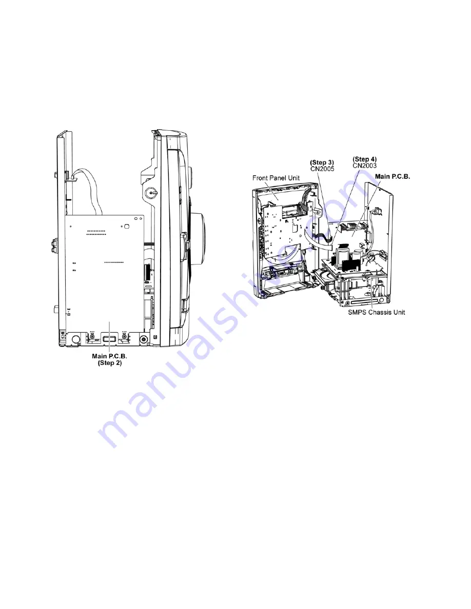
13 Service Position
Note: For description of the disassembly procedures, see
the Section 11.
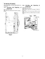
13.1. Checking and Repairing of
Main P.C.B.
Step 1
Remove Top Cabinet.
Step 2
Main P.C.B. can be checked & repaired at its original
position.
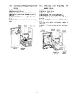
13.2. Checking and Repairing of
Panel P.C.B.
Step 1
Remove Top Cabinet.
Step 2
Remove Front Panel Unit.
Step 3
Attach 5P Cable Wire to the connector (CN2005) on
Main P.C.B..
Step 4
Attach 17P FFC to the connector (CN2003) on Main
P.C.B..
Step 5
Panel P.C.B. can be checked and repaired as diagram
shown.
64
Содержание SA-AKX14LM-K
Страница 14: ...5 General Introduction 5 1 Media Information 14 ...
Страница 15: ...6 Location of Controls and Components 6 1 Remote Control Key Button Operation 15 ...
Страница 16: ...6 2 Main Unit Key Button Operation 16 ...
Страница 17: ...7 Installation Instructions 7 1 Speaker and A C Connection 17 ...
Страница 28: ... 3 D Amp IC Operation Control 28 ...
Страница 33: ...11 2 Main Components and P C B Locations 33 ...
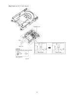
Страница 63: ...Step 9 Ground the 24P FFC with a short pin 63 ...
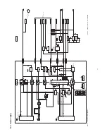
Страница 67: ...14 Simplified Block Diagram 14 1 Overall Simplified Block Diagram 67 ...
Страница 68: ...14 2 Power Block Diagram 68 ...
Страница 103: ...20 2 Electrical Replacement Part List 103 ...


