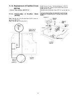
11.7. Disassembly of Remote Sensor
P.C.B.
•
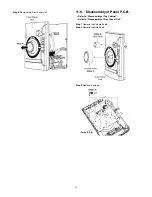
Refer to “Disassembly of Top Cabinet”.
•
Refer to “Disassembly of Front Panel Unit”.
•
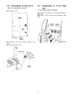
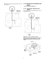
Refer to (Step 1) to (Step 5) of item 11.6.
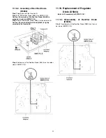
Step 1
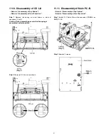
Remove the Remote Sensor P.C.B..
Caution: During assembling, ensure that Remote Sensor
P.C.B. is properly inserted & fully connected to Panel
P.C.B..
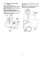
11.8. Disassembly of USB P.C.B.
•
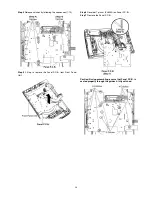
Refer to “Disassembly of Top Cabinet”.
•
Refer to “Disassembly of Front Panel Unit”.
•
Refer to (Step1) to (Step5) of item 11.6.
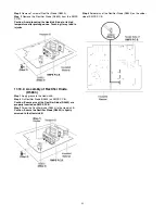
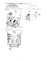
Step 1
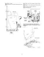
Remove 1 screw.
Step 2
Remove the USB Unit.
Step 3
Release 1 catch.
Step 4
Remove the USB P.C.B..
39
Содержание SA-AKX14LM-K
Страница 14: ...5 General Introduction 5 1 Media Information 14 ...
Страница 15: ...6 Location of Controls and Components 6 1 Remote Control Key Button Operation 15 ...
Страница 16: ...6 2 Main Unit Key Button Operation 16 ...
Страница 17: ...7 Installation Instructions 7 1 Speaker and A C Connection 17 ...
Страница 28: ... 3 D Amp IC Operation Control 28 ...
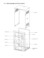
Страница 33: ...11 2 Main Components and P C B Locations 33 ...
Страница 63: ...Step 9 Ground the 24P FFC with a short pin 63 ...
Страница 67: ...14 Simplified Block Diagram 14 1 Overall Simplified Block Diagram 67 ...
Страница 68: ...14 2 Power Block Diagram 68 ...
Страница 103: ...20 2 Electrical Replacement Part List 103 ...


