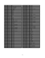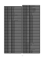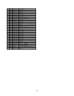
19.9.2.
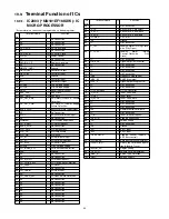
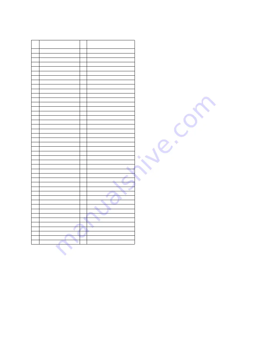
IC900(C0HBA0000295): IC FL
Driver
Pin
No.
Terminal Name
I/O
Function
1
/CS
I
Chip Selection Input
2
/RD
I
Read Clock Input
3
/WR
I
Write Clock Input
4
DATA
I/O Serial Data Input
5
VSS
I
Negative Power Supply
6
VLCD
I
LCD Power Input
7
VDD
I
Positive Power Supply
8
BZ
O Tone Frequency Output Pair
9
COM0
O Common Output 0
10
COM1
O Common Output 1
11
COM2
O Common Output 2
12
COM3
O Common Output 3
13
SEG31
O Segment Output 31
14
SEG30
O Segment Output 30
15
SEG29
O Segment Output 29
16
SEG28
O Segment Output 28
17
SEG27
O Segment Output 27
18
SEG26
O Segment Output 26
19
SEG25
O Segment Output 25
20
SEG24
O Segment Output 24
21
SEG23
O Segment Output 23
22
SEG22
O Segment Output 22
23
SEG21
O Segment Output 21
24
SEG20
O Segment Output 20
25
SEG19
O Segment Output 19
26
SEG18
O Segment Output 18
27
SEG17
O Segment Output 17
28
SEG16
O Segment Output 16
29
SEG15
O Segment Output 15
30
SEG14
O Segment Output 14
31
SEG13
O Segment Output 13
32
SEG12
O Segment Output 12
33
SEG11
O Segment Output 11
34
SEG10
O Segment Output 10
35
SEG9
O Segment Output 9
36
SEG8
O Segment Output 8
37
SEG7
O Segment Output 7
38
SEG6
O Segment Output 6
39
SEG5
O Segment Output 5
40
SEG4
O Segment Output 4
41
SEG3
O Segment Output 3
42
SEG2
O Segment Output 2
43
SEG1
O Segment Output 1
44
SEG0
O Segment Output 0
97
Содержание SA-AKX14LM-K
Страница 14: ...5 General Introduction 5 1 Media Information 14 ...
Страница 15: ...6 Location of Controls and Components 6 1 Remote Control Key Button Operation 15 ...
Страница 16: ...6 2 Main Unit Key Button Operation 16 ...
Страница 17: ...7 Installation Instructions 7 1 Speaker and A C Connection 17 ...
Страница 28: ... 3 D Amp IC Operation Control 28 ...
Страница 33: ...11 2 Main Components and P C B Locations 33 ...
Страница 63: ...Step 9 Ground the 24P FFC with a short pin 63 ...
Страница 67: ...14 Simplified Block Diagram 14 1 Overall Simplified Block Diagram 67 ...
Страница 68: ...14 2 Power Block Diagram 68 ...
Страница 103: ...20 2 Electrical Replacement Part List 103 ...


