background image

FP2 S

LINK Unit

Construction and Wiring

4

3

4.1 Wiring Methods for S

LINK Main Unit

4.1

Wiring Methods for S

LINK Main Unit

There are two method of wiring an S

LINK system standard wiring and loop wiring each

having its advantage.

The connections are described below. For detailed information, refer to the “S

LINK

Construction Manual.”

4.1.1

Wiring to the S

LINK Terminal Block

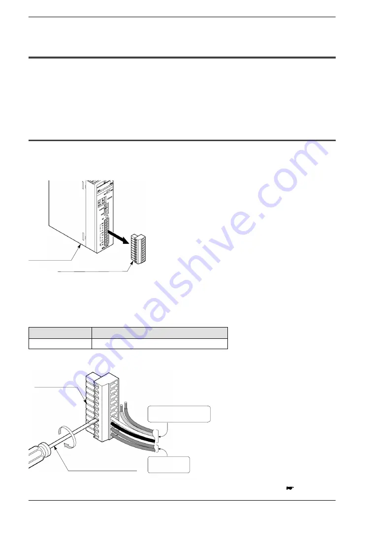
The S

LINK terminal block is detachable. Wiring the S

LINK terminal block while it is

detached from the unit allows the wiring to be done without detaching the whole main

unit.

S

LINK terminal block

S

LINK unit

Terminal block: MC1.5/10

ST

3.5 (Made by Phoenix Contact Co.; provided as an

accessory)
The wires noted below should be used.

Suitable wiring

Size

Nominal cross

section surface area

AWG #20 to 16

0.5 to 1.25 mm

2

We recommend using the appropriate screwdriver to tighten the wiring.

Power sup-

ply cable

S

LINK terminal

block

Appropriate screwdriver

S

LINK exclusive

flat cable

next page

Содержание S-Link FP2

Страница 1: ......

Страница 2: ...ion use this product at the values less than the maximum of the characteristics and performance that are assured in these specifications Do not dismantle or remodel the product It could cause excessive exothermic heat or smoke generation Do not touch the terminal while turning on electricity It could lead to an electric shock Use the external devices to function the emergency stop and interlock ci...

Страница 3: ...vely for the FP2 programmable controller and is equipped with numerous functions that make it easy to use the S LINK with the FP2 This hardware manual describes the functions installation wiring and operation of the FP2 S LINK unit CPU with S LINK Please make sure you understand the material contained in this manual before using your equipment ...

Страница 4: ...cations 2 8 2 4 S LINK Controller Specifications 2 9 Chapter 3 I O Assignments 3 1 An Overview of I O Assignments 3 3 3 2 Specifying the Number of Input Output Points 3 4 3 3 Assigning Inputs and Outputs 3 8 3 3 1 User Determined Assignments 3 8 3 3 2 I O Mounting Assignments 3 9 3 3 3 Automatic Assignments 3 9 3 4 Slot of CPU with S LINK 3 10 Chapter 4 Construction and Wiring 4 1 Wiring Methods f...

Страница 5: ...Addresses 5 13 Chapter 6 Shared Memory 6 1 Configuration of the Shared Memory 6 3 6 2 Shared Memory Reading Program 6 4 Chapter 7 What To Do If An Error Occurs 7 1 Judging Errors From the Error Indicators 7 3 7 1 1 ERR1 is Lighted 7 3 7 1 2 ERR1 and ERR3 are Lighted 7 4 7 1 3 ERR4 is Lighted 7 4 7 2 Address Display 7 5 7 3 Judging Error Displays 7 6 7 3 1 Only a Numeric Value is Displayed 7 6 7 3 ...

Страница 6: ...ns FP2 S LINK Unit iv Special Precautions This manual is the instruction manual for the FP2 S LINK unit CPU with S LINK For detailed information about the S LINK refer to the S LINK Design manual and Construction manual ...

Страница 7: ...Chapter 1 Selecting the Right Equipment 1 1 Features 1 3 1 2 Types 1 5 1 3 Installation Restrictions 1 6 1 3 1 FP2 S LINK Unit 1 6 1 3 2 CPU with S LINK 1 7 1 4 Current Consumption 1 8 ...

Страница 8: ...Selecting the Right Equipment FP2 S LINK Unit 1 2 ...

Страница 9: ...ection S LINK exclu sive flat cable Maximum length 200 m 400 m when a booster is used S LINK I O device Branch cable T branch hook up connector T branch hook up connector Example Loop wiring The S LINK exclusive flat cable from is run from the controller and the end is connected back to the controller The loop can have a maximum length of 200 meters The end connector is connected at approximately ...

Страница 10: ...ser may select combinations offering up to a total of 128 inputs and outputs For the CPU with S LINK two internal S LINK controllers are provided and two input output channels 128 points x 2 can be used The inputs and outputs are handled by the program just like ordinary ones The S LINK system can be easily monitored by reading shared memory data A broad range of peripheral devices for the S LINK ...

Страница 11: ...Types 1 2 Types Name Internal functions Model no FP2 S LINK unit 128 input output points using S LINK FP2 SL2 CPU with S LINK Discontinued Product Two input output channels 128 points x 2 using S LINK FP2 C1SL Discontinued Product p p p g FP2 CPU function ...

Страница 12: ...pansion backplane it may be installed at any position Expansion backplane CPU backplane Can be installed at any position Can be installed at any position Expansion cable The FP2 S LINK unit may be installed in any slot other than those used to install the power supply unit and the CPU Any number may be installed as long as the number is within the range of I O points that can be controlled by the ...

Страница 13: ...y in the position to the right of and adjacent to the power supply unit on the CPU backplane the position where the CPU can normally be installed It cannot be installed and used on the expansion backplane Cannot be installed on expansion backplane CPU backplane CPU with S LINK Cannot be installed here Expansion cable Expansion backplane ...

Страница 14: ...en configuring the system the usage conditions of other units should be taken into consideration and included in the capacity of the power supply unit Name Model no Current consumption 5V power supply FP2 S LINK unit FP2 SL2 130mA max CPU with S LINK FP2 C1SL 670mA max Note For information on the internal current consumption of other units refer to the FP2 FP2SH User s Manual and the manual for th...

Страница 15: ...Chapter 2 Specifications 2 1 Parts Related to S LINK Operation 2 3 2 2 Parts Related to CPU Operation CPU with S LINK 2 7 2 3 Specifications 2 8 2 4 S LINK Controller Specifications 2 9 ...

Страница 16: ...Specifications FP2 S LINK Unit 2 2 ...

Страница 17: ...h MONITOR switch System SET button S LINK terminal block ADDRESS display selector switch 1 Transmission indicator SEND The CPU with S LINK is equipped with Channel 1 and Channel 2 indicator LEDs Green During normal transmission at the same time as the transmission indicator SEND blinks 2 ERROR indicators The CPU with S LINK is equipped with Channel 1 and Channel 2 error indicators These light if a...

Страница 18: ...and Channel 2 I O indicators The on off status of the various S LINK system addresses are displayed in units of eight points The address to be displayed is selected using the 6 MONITOR switch For detailed information refer to section 5 4 5 3 Confirming the On Off Status of Addresses 4 RUN CHK selector switch Set to RUN This is the normal operation mode Set to CHK This is the Check mode for detaile...

Страница 19: ...ints Note With a CPU with S LINK the above is displayed for the channel selected using the 10 ADDRESS display selector switch 6 MONITOR switch The CPU with S LINK is equipped with Channel 1 and Channel 2 The display addresses for the 3 I O indicators corresponding to the S LINK I O device addresses are specified in units of 8 points For detailed information refer to section 5 4 5 3 Confirming the ...

Страница 20: ...If an error occurs Each time the system SET button is pressed all of the addresses where errors have occurred are displayed by the 5 ADDRESS display in a sequential blinking display starting with the smallest when ERR4 occurs Note If the RUN CHK selector switch is set to the RUN position and the system SET button is pressed while an error is in effect only the number of units that can be confirmed...

Страница 21: ...es 2 Initialize test switch is used to clear the errors initialize the operation memory and set the test operation mode 3 Mode selector is used to change the operation mode 4 COM port RS232C is used to connect a computer or general serial devices with RS232C port 5 Tool port RS232C is used to connect a programming tool 6 Operation condition switch is used to set the baud rate of the programming to...

Страница 22: ...d ground for 1 minute 1500V AC between S LINK terminal block and AC outer terminal for 1 minute Insulation resistance 100MΩ min between S LINK termi nal block and ground using 500V DC mega ohmmeter 100MΩ min between S LINK termi nal block and AC outer terminal us ing 500V DC mega ohmmeter 100MΩ min between S LINK termi nal block and ground using 500V DC mega ohmmeter 100MΩ min between AC outer ter...

Страница 23: ...onal time divided multiple signal transmission Synchronization method Bit synchronization frame synchronization Transmission protocol S LINK protocol Transmission speed 28 5 kbps Transmission distance 128 I O signals can be transmitted over a pair of wires up to a distance to 200m max 400m when a booster is used note 2 g p p max 400m when a booster is used FAN out note 2 320 Connection method T br...

Страница 24: ...tailed information on current consumption refer to Determining the Power Supply Capacitance in the S LINK Design Manual 2 For information on the booster and FAN out refer to the S LINK Design Manual 3 The number of input and output points is automatically reflected in input X and output Y ...

Страница 25: ...I O Assignments 3 3 3 2 Specifying the Number of Input Output Points 3 4 3 3 Assigning Inputs and Outputs 3 8 3 3 1 User Determined Assignments 3 8 3 3 2 I O Mounting Assignments 3 9 3 3 3 Automatic Assignments 3 9 3 4 Slot of CPU with S LINK 3 10 ...

Страница 26: ...I O Assignments FP2 S LINK Unit 3 2 ...

Страница 27: ...e S LINK unit X10 X11 X2E X2F Addresses 0 1 30 31 16 point input unit I O setting switch MODE is set to 4 Y30 31 Y4E Y4F Addresses 32 33 62 63 32 output points 32 input points X10 to X2F Y30 to Y4F Contents of the illustration Power supply unit standard CPU 16 point input unit S LINK unit installed beside these I O numbers assigned to the S LINK unit are X10 to X 2F 32 points and Y30 to Y4F 32 poi...

Страница 28: ... 32 1 0 Y n 0 to Y n 3 F 64 0 to 63 0 64 64 2 0 Y n 0 to Y n 7 F 128 0 to 127 0 128 128 3 X n 0 to X n 1 F 32 0 0 to 31 32 0 32 4 X n 0 to X n 1 F 32 Y n 2 0 to Y n 3 F 32 0 to 31 32 to 63 32 32 64 5 X n 0 to X n 1 F 32 Y n 2 0 to Y n 5 F 64 0 to 31 32 to 95 32 64 96 6 X n 0 to X n 3 F 64 0 0 to 63 64 0 64 7 X n 0 to X n 3 F 64 Y n 4 0 to Y n 5 F 32 0 to 63 64 to 95 64 32 96 8 X n 0 to X n 3 F 64 ...

Страница 29: ...is n 1 With S LINK unit installed in a standard CPU n 0 If both input and output are specified always specify the I O number for the input first The I O setting switch MODE settings should not be changed after the power supply has been turned on This causes a CPU error to occur The number of input output points selected for the S LINK unit or CPU with S LINK serves as the number of I O points for ...

Страница 30: ...s 0 1 62 63 Y40 Y41 Y7E Y7F Addresses 64 65 126 127 64 output points 64 input points X0 to X3F Y40 to Y7F Example 2 Example where another unit has been installed between the S LINK unit and the standard CPU and the I O setting switch MODE has been set to 4 16 point input unit I O setting switch MODE set to 4 X20 X21 X3E X3F Addresses 0 1 30 31 Y40 Y41 Y5E Y5F Addresses 32 33 62 63 32 output points...

Страница 31: ...setting switch MODE set to 6 on the S LINK 1 side and to 4 on the S LINK 2 side S LINK 2 I O setting switch MODE set to 4 X40 X41 X5E X5F Addresses 0 1 30 31 Y60 Y61 Y7E Y7F Addresses 32 33 62 63 32 output points 32 input points X40 to X5F Y60 to Y7F X0 to X3F X0 X1 X3E X3F Addresses 0 1 62 62 64 input points S LINK 1 I O setting switch MODE set to 6 ...

Страница 32: ... numbers being off even if the unit is installed in the wrong slot or there are empty slots The number of I O points selected with the I O setting switch MODE should be assigned to the slot where the unit is installed Example When the I O setting switch MODE is set to 4 there are 64 points 16 point input unit I O setting switch MODE set to 4 X20 to X3F Y40 to Y5F Note Input and output for the S LI...

Страница 33: ...he same as when Automatic Assignments is implemented 3 3 3 Automatic Assignments If the power supply to the PLC is turned on after a unit is installed assignments are made automatically according to the status of the unit The unit has the number of I O points selected using the I O setting switch MODE Example The unit has 96 points when the I O setting switch MODE is set to 7 Refer to 3 2 Specifyi...

Страница 34: ...ot The S LINK unit expands the functions of the slot which it occupies by providing the functions of two S LINK units in one slot When I O assignments are made the S LINK unit component is treated as though there were two slots with an individual S LINK unit installed in each Example 7 module type backplane Same as if one slot is added and two S LINK units are installed Slot no Power supply CPU S ...

Страница 35: ...hapter 4 Construction and Wiring 4 1 Wiring Methods for S LINK Main Unit 4 3 4 1 1 Wiring to the S LINK Terminal Block 4 3 4 1 2 Standard Wiring 4 4 4 1 3 Loop Wiring 4 5 4 2 S LINK Main Power Supply 4 6 ...

Страница 36: ...Construction and Wiring FP2 S LINK Unit 4 2 ...

Страница 37: ...LINK terminal block is detachable Wiring the S LINK terminal block while it is detached from the unit allows the wiring to be done without detaching the whole main unit S LINK terminal block S LINK unit Terminal block MC1 5 10 ST 3 5 Made by Phoenix Contact Co provided as an accessory The wires noted below should be used Suitable wiring Size Nominal cross section surface area AWG 20 to 16 0 5 to 1...

Страница 38: ...Electric Works SUNX Co Ltd Order no Phoenix Contact Co model no AFP0806 Model no Product no SZS 0 4 2 5 1205037 4 1 2 Standard Wiring Only the Out A main cable of the S LINK terminal block is used Terminal name Color of connecting cable Out A Main cable 24V Brown Main cable 0V Blue D White G Black Note For information on power supply wiring refer to section 4 2 S LINK Power Supply For information ...

Страница 39: ... the other end to output B Terminal name Color of connecting cable Output B 24V Brown 0V Blue D White G Black Output A 24V Brown 0V Blue D White G Black Note For information on power supply wiring refer to section 4 2 S LINK Power Supply For information on wiring and connecting S LINK devices refer to the S LINK Construction Manual Loop wiring Output B S LINK exclusive flat cable S LINK unit Power...

Страница 40: ...overall S LINK system is calculated by referring to the section entitled Determining the Power Supply in the S LINK Design Manual For standard purposes a power supply exceeding 24V DC 1 6 A should be selected Example The power supply is connected to IN 24V 0V on the S LINK terminal block External power supply S LINK exclusive flat cable S LINK unit Power supply cable From external power supply Bro...

Страница 41: ...the Address 5 7 5 4 2 For a CPU With S LINK 5 8 5 4 3 What to do if an Error Occurs 5 8 5 4 4 Results and Processing of Address Recognition 5 9 5 4 5 Confirming Connected Stations 5 10 5 4 5 1 Confirming All Recognized Addresses 5 10 5 4 5 2 Confirming All Addresses Where Errors Have Occurred 5 12 5 4 5 3 Confirming the On Off Status of Addresses 5 13 ...

Страница 42: ...Operation FP2 S LINK Unit 5 2 ...

Страница 43: ...upplies on at the same time 1 S LINK main power supply 2 Main unit FP2 power supply If a local power supply is being used for I O devices connected to the system and for S LINK I O devices make sure the local power supply is turned on before the S LINK main power supply or turn both power supplies on at the same time 1 Local power supply 3 Main unit FP2 power supply 2 S LINK main power supply brow...

Страница 44: ...nit 5 4 5 1 Starting Operation If using the booster local power supply start up the booster before the S LINK main power supply 3 Main unit FP2 power supply 2 S LINK main power supply 1 Booster local power supply brown blue ...

Страница 45: ...ply local power supply or turn off the main unit S LINK main and local power supplies at the same time If using the booster local power supply turn off the power supplies in the following sequence main unit S LINKmain power supply booster local power supply or turn off the main unit S LINK main and booster local power supplies at the same time Note When turning off the power supplies any S LINK de...

Страница 46: ...or the S LINK input output data to be refreshed A timer or similar device should be used to boot the program so that the program boots after the data has been refreshed Approx 1 8 seconds Power supply turned on S LINK input output data refreshed Note Make sure an adequate time period is taken into consideration allowing time after booting the system for S LINK input to pass through the b contact a...

Страница 47: ...witch on the S LINK unit to the RUN position If the S LINK system is being operated for the first time turn on the power supply and then press the system SET button Explanation When the system SET button is pressed the number of connected devices recognized by S LINK unit blinks on the address display in hexadecimal HEX number and then a shaped character rotates in the clockwise direction If the a...

Страница 48: ...em SET button each time the power is turned on When the power supply is switched on for the first time after completing the wiring of S LINK system an arbitrary error display may appear This does not indicate any abnormal operation If the system SET button is pressed this display is erased If an error address is displayed during normal use of the device do not press the system SET button Pressing ...

Страница 49: ...ors in the S LINK during operation will be carried out based on the connection status stored in the memory at this time If there is a problem The displayed numeric value does not match the actual number of S LINK I O devices that are connected to the S LINK system Explanation There is a S LINK I O device that has not been correctly recognized Turn off the power supply and check carefully for erron...

Страница 50: ...CHK selector switch to the CHK position The S LINK unit switches to check CHK mode The number of recognized connected devices blinks At this time even if booster is connected it is not included in the number of connected devices RUN CHK selec tor switch 2 Press the system SET button The smallest of the recognized addresses is displayed After this each time the system SET button is pressed the reco...

Страница 51: ...I O Device Address Recognition Example Number of connected units is displayed in a blinking display Note After confirmation has been made always set the RUN CHK selector switch back to the RUN position The display reverts to the normal display ...

Страница 52: ...s broken or a problem has occurred in an S LINK I O device you can check the address of the S LINK I O device where the error has occurred Note For an explanation of the contents of the address display refer to section 7 3 Judging Error Displays Procedure 1 Set the RUN CHK selector switch to CHK position The S LINK unit switches to check CHK mode RUN CHK selector switch next page ...

Страница 53: ...curred blink successively in the ascending order Note After confirmation is made always set the RUN CHK selector switch back to the RUN position 5 4 5 3 Confirming the On Off Status of Addresses It is possible to confirm the on off status of the various addresses in the S LINK Procedure 1 Using the MONITOR switch select the numeric value where the address to be confirmed is stored MONITOR switch n...

Страница 54: ... to be confirmed Displayed Addresses I O indicator MONITOR switch indicator 0 1 2 3 4 5 6 7 8 9 A B C D E F 0 0 8 16 24 32 40 48 56 64 72 80 88 96 104 112 120 1 1 9 17 25 33 41 49 57 65 73 81 89 97 105 113 121 2 2 10 18 26 34 42 50 58 66 74 82 90 98 106 114 122 3 3 11 19 27 35 43 51 59 67 75 83 91 99 107 115 123 4 4 12 20 28 36 44 52 60 68 76 84 92 100 108 116 124 5 5 13 21 29 37 45 53 61 69 77 85...

Страница 55: ...Chapter 6 Shared Memory 6 1 Configuration of the Shared Memory 6 3 6 2 Shared Memory Reading Program 6 4 ...

Страница 56: ...Shared Memory FP2 S LINK Unit 6 2 ...

Страница 57: ...on of unit S LINK device addresses where errors occur when they occur and the number of S LINK devices connected to the S LINK system is stored in the memory Data can be read from and written to the CPU using high level instructions Reading data from the shared memory using programming software Procedure 1 Online Read shared memory 2 Press the Read PC to read the status Reading data from the share...

Страница 58: ...rom the memory of the intelligent unit Types of memory areas that can be specified specified in word units May be specified May not be specified Operand WX WY WR WL SV EV DT LD FL I0 to Constant Index modifier to ID K H modifier S1 Slot number specification S2 First address to be read from intelligent unit memory n No of words to be read D First no of area where data to be read is stored Explanati...

Страница 59: ...counted as slot numbers 14 slots no of slots on backplane Power supply CPU Power supply 14 module type CPU backplane 16 slots slots counted as slot numbers 14 slots no of slots on backplane 14 module type expansion backplane For a CPU with S LINK The slot numbers 0 and 1 are assigned to S LINK1 and S LINK2 respectively 16 slots slots counted as slot numbers 14 slots no of slots on backplane CPU wi...

Страница 60: ...e S LINK unit is installed on the backplane in the position indicated in the illustration Power supply unit CPU S LINK unit I O setting switch MODE is set to 7 X0 to X3F 64 points Y40 to Y5F 32 points Note If the FP2 is configured differently the slot number and the first device containing the data to be read should be changed ...

Страница 61: ...T5 First device where data to be read is stored Reading of control flag error flag Reading of the following No of units where error occurred No of units connected Total no of inputs outputs No of input points No of output points Reading of the following Unit where error occurred Connected unit Results of execution ERR1 Control flag error flag R8 to R15 off ERR2 not used ERR3 ERR4 S LINK communicat...

Страница 62: ...Shared Memory FP2 S LINK Unit 6 8 6 2 Shared Memory Reading Program ...

Страница 63: ...e Error Indicators 7 3 7 1 1 ERR1 is Lighted 7 3 7 1 2 ERR1 and ERR3 are Lighted 7 4 7 1 3 ERR4 is Lighted 7 4 7 2 Address Display 7 5 7 3 Judging Error Displays 7 6 7 3 1 Only a Numeric Value is Displayed 7 6 7 3 2 A Numeric Value and Decimal Points are Displayed 7 6 ...

Страница 64: ...What To Do If An Error Occurs FP2 S LINK Unit 7 2 ...

Страница 65: ...D G line Erroneous voltage level between D G line Broken or disconnected wire or error in I O unit S LINK device 7 1 1 ERR1 is Lighted Lighted Note The short circuit protective function is not canceled simply by eliminating the cause of the error Always turn off the S LINK main and local power supplies the power supply between D G line and turn it back on again ...

Страница 66: ...upplies on again 7 1 3 ERR4 is Lighted Lighted There is a broken or disconnected wire in the S LINK or there is an error in an S LINK device If this happens set the RUN CHK selector switch to the CHK position and press the system SET button This displays the address of the S LINK I O device where the error occurred in the address display window if errors have occurred at multiple addresses the dis...

Страница 67: ...t side open are displayed here If an error occurs at an address in the S LINK an S LINK device that address is displayed as a numeric value Example If an error occurs example the ad dress is displayed When operating normally the display ro tates For a CPU with S LINK use the address display selector switch to select the channel where operation is to be checked ...

Страница 68: ... where an error has occurred Turn off the power supply to the S LINK the power supply between D G line and correct the error Then turn on the power supply to the S LINK the power supply between D G line 7 3 2 A Numeric Value and Decimal Points are Displayed Example This is a hexadecimal number display Decimal points More than one error has occurred The numeric value that is displayed indicates the...

Страница 69: ...e RUN CHK selector switch to the CHK position and press the system SET button Turn off the power supply to the S LINK the power supply between D G line and correct the error Then turn on the power supply to the S LINK the power supply between D G line Note Set the RUN CHK selector switch to the CHK position before pressing the system SET button ...

Страница 70: ...What To Do If An Error Occurs FP2 S LINK Unit 7 8 7 3 Judging Error Displays ...

Страница 71: ...apter 8 Appendix 8 1 Table of Shared Memory Addresses 8 3 8 1 1 Error Address Quick Reference Table 8 5 8 1 2 Connection Unit Address Quick Reference Table 8 5 8 2 S LINK Address Quick Reference Table 8 6 ...

Страница 72: ...Appendix FP2 S LINK Unit 8 2 ...

Страница 73: ...rt circuit protective function continues to be active as long as the S LINK power supply is on ΣIf the S LINK power supply is off Bit 0 ERR1 and Bit 2 ERR3 1 ΣBit 3 ERR4 1 is retained To cancel it the FP2 power supply must be turned off and then on again or the system SET button pressed and reset For information on settings refer to section 5 4 S LINK IO Device Address Recognition ΣIf communicatio...

Страница 74: ...tion frame has been completed is used to check whether the output data has been transferred to the S LINK output unit If any numeric value other than 0 is written after the output data has been written the value automatically becomes 0 after the output data has been transferred to the S LINK output unit Checking to make sure that the value has been changed to 0 in the program and then writing the ...

Страница 75: ...3 122 121 120 119 118 117 116 115 114 113 112 1 error 0 normal 8 1 2 Connection Unit Address Quick Reference Table If 1 is written for a bit an S LINK I O device is connected at that address Bit Address 15 14 13 12 11 10 9 8 7 6 5 4 3 2 1 0 H 10 15 14 13 12 11 10 9 8 7 6 5 4 3 2 1 0 H 11 31 30 29 28 27 26 25 24 23 22 21 20 19 18 17 16 H 12 47 46 45 44 43 42 41 40 39 38 37 36 35 34 33 32 H 13 63 62...

Страница 76: ...C X1C Y1C 28 1C X2C Y2C 44 2C XD YD 13 D X1D Y1D 29 1D X2D Y2D 45 2D XE YE 14 E X1E Y1E 30 1E X2E Y2E 46 2E XF YF 15 F X1F Y1F 31 1F X2F Y2F 47 2F I O dd S LINK address I O dd S LINK address I O dd S LINK address address Decimal Hexa decimal address Decimal Hexa decimal address Decimal Hexa decimal X30 Y30 48 30 X40 Y40 64 40 X50 Y50 80 50 X31 Y41 49 31 X41 Y41 65 41 X51 Y51 81 51 X32 Y42 50 32 X4...

Страница 77: ...113 71 X62 Y62 98 62 X72 Y72 114 72 X63 Y63 99 63 X73 Y73 115 73 X64 Y64 100 64 X74 Y74 116 74 X65 Y65 101 65 X75 Y75 117 75 X66 Y66 102 66 X76 Y76 118 76 X67 Y67 103 67 X77 Y77 119 77 X68 Y68 104 68 X78 Y78 120 78 X69 Y69 105 69 X79 Y79 121 79 X6A Y6A 106 6A X7A Y7A 122 7A X6B Y6B 107 6B X7B Y7B 123 7B X6C Y6C 108 6C X7C Y7C 124 7C X6D Y6D 109 6D X7D Y7D 125 7D X6E Y6E 110 6E X7E Y7E 126 7E X6F Y...

Страница 78: ...Appendix FP2 S LINK Unit 8 8 8 2 S LINK Address Quick Reference Table ...

Страница 79: ... Date Description of changes ARCT1F275E ACG M275E ARCT1F275E 1 ACG M275E 1 ARCT1F275E 2 ACG M275E 2 ARCT1F275E 3 ARCT1F275E 4 NOV 1999 NOV 2006 NOV 2008 AUG 2011 SEP 2012 First edition Second edition Third edition Fourth edition Fixed Errors 5th edition Fixed Errors ...

Страница 80: ...FP2 S LINK Unit Record of changes R 2 ...

Страница 81: ......

Страница 82: ......

Отзывы: