background image

Chapter 1

Preparation — Preparing the remote control

34 - ENGLISH

Preparing the remote control

Inserting and removing the batteries

(ii)

(i)

Fig. 1

Fig. 2

1)  Open the cover. (Fig. 1)

2)  Insert the batteries and close the cover (insert the 

m

 side first). (Fig. 2)


f

When removing the batteries, perform the steps in reverse order.

When using the multiple projectors

When you use the multiple projectors together, you can operate all the projectors simultaneously or each projector 

individually using a single remote control, if a unique ID number is assigned to each projector.

When using the projectors by setting the ID numbers, set the ID number of the projector body after initial settings 

have been completed. Then, set the ID number of the remote control. For initial settings, refer to “When the initial 

setting screen is displayed” (

x

 page 59).

The factory default ID number of the projector (projector body and remote control) is set to [ALL], so you can use it 

as it is. Set the ID numbers of the projector body and remote control as necessary.
For details on setting the ID number of the remote control, refer to “Setting ID number of the remote control” 

(

x

 page 77).

Note


f

Set the ID number of the projector body from the [PROJECTOR SETUP] menu 

 [PROJECTOR ID].

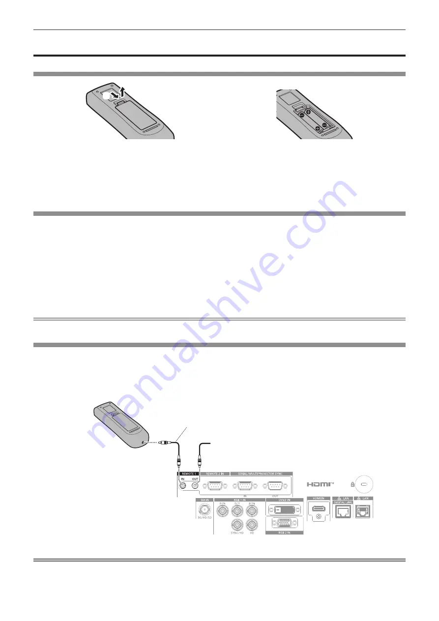
Connecting the remote control to the projector with a cable

To simultaneously control multiple projectors next to each other with one remote control, connect the remote 

control with a commercially available M3 stereo mini jack cable using the <REMOTE 1 IN>/<REMOTE 1 OUT> 

terminals.
The remote control is effective even in places where an obstacle stands in the light path or where devices are 

susceptible to outside light.

Connecting terminals

Connecting to a second projector

M3 stereo mini jack cable (commercially available)

Remote control

Connecting to the remote 

control wired terminal

Attention


f

Use a cable that is 15 m (49'3") or shorter, with 2 core shielded. The remote control may not operate when the length of the cable exceeds 

15 m (49'3") or when the shielding of the cable is inadequate.

Содержание PT-RZ990

Страница 1: ...odel the standard zoom lens supplied z z for other countries or regions B Black model the standard zoom lens supplied LB Black model the lens sold separately W White model the standard zoom lens suppl...

Страница 2: ...function shutter synchronization function 53 Chapter 3 Basic Operations Switching on off the projector 56 Connecting the power cord 56 Power indicator 57 Switching on the projector 58 When the initial...

Страница 3: ...ON BUTTON 151 STATUS 151 DATA CLONING 153 SAVE ALL USER DATA 155 LOAD ALL USER DATA 155 INITIALIZE 155 SERVICE PASSWORD 156 TEST PATTERN menu 157 TEST PATTERN 157 SIGNAL LIST menu 158 Registering new...

Страница 4: ...nction 212 Control commands via LAN 216 SERIAL MULTI PROJECTOR SYNC IN SERIAL MULTI PROJECTOR SYNC OUT terminals 219 REMOTE 2 IN terminal 223 RGB 2 IN terminal 224 Upgrade Kit 224 List of compatible s...

Страница 5: ...earthing type mains socket This is a safety feature If you are unable to insert the plug into the mains socket contact an electrician Do not defeat the purpose of the earthing plug WARNING This equip...

Страница 6: ...at the light emitted from the lens while the projector is being used As with any bright source do not stare into the direct beam RG2 IEC 62471 5 2015 Indicated on the projector Notice on laser for US...

Страница 7: ...ols or adjustments or performance of procedures other than those specified herein may result in hazardous radiation exposure CAUTION North Middle South America Power Supply This Projector is designed...

Страница 8: ...a computer room as defined in the Standard for the Protection of Electronic Computer Data Processing Equipment ANSI NFPA 75 f f For permanently connected equipment a readily accessible disconnect dev...

Страница 9: ...nt has been tested and found to comply with the limits for a Class A digital device pursuant to part 15 of the FCC Rules These limits are designed to provide reasonable protection against harmful inte...

Страница 10: ...13 amp socket If a new plug is to be fitted please observe the wiring code as shown below If in any doubt please consult a qualified electrician WARNING THIS APPLIANCE MUST BE EARTHED IMPORTANT The w...

Страница 11: ...ction lens which the hazard distance exceeds 1 m 39 3 8 and is categorized as risk group 3 is as follows Projection lens Model No Risk group ET DLE250 Risk group 3 1 ET DLE350 ET DLE450 1 When the pro...

Страница 12: ...follows Unit m Projection lens Model No HD 1 D1 2 D2 2 D3 2 D4 2 ET DLE250 1 4 0 40 0 27 0 52 0 39 ET DLE350 2 2 0 40 0 27 0 52 0 39 ET DLE450 3 2 0 40 0 27 0 51 0 38 1 HD Hazard Distance 2 The value...

Страница 13: ...lure to observe this will result in electric shocks Use an outlet supporting 15 A independently Using an outlet together with another device may result in fires due to heat generation Do not overload...

Страница 14: ...eiling should only be carried out by a qualified technician If installation is not carried out and secured correctly it can cause injury or accidents such as electric shocks r r ACCESSORIES Do not use...

Страница 15: ...projector in extremely hot locations Doing so will cause the outer casing or internal components to deteriorate or result in fire f f Take particular care in locations exposed to direct sunlight or n...

Страница 16: ...fire or explode which may result in fire or contamination of surrounding area r r MAINTENANCE Ask your dealer about cleaning inside the projector every 20 000 hours of usage as an estimated duration...

Страница 17: ...do pela bateria pode irritar a garganta danificar o lacre do inv lucro ou o vazamento provocar calor ruptura da blindagem e produzir fogo devido ao curto circuito dos terminais N o incinere nem aque a...

Страница 18: ...tes the following software 1 the software developed independently by or for Panasonic Corporation 2 the software owned by third party and licensed to Panasonic Corporation 3 the software licensed unde...

Страница 19: ...ort including horizontal vertical and portrait utilizing the characteristics of solid state light source and a lineup of various optional lenses Long life and high reliability The maintenance cost for...

Страница 20: ...20 ENGLISH Chapter 1 Preparation This chapter describes things you need to know or check before using the projector...

Страница 21: ...f f Do not transport the projector with the adjustable feet extended Doing so may damage the adjustable feet Cautions when installing r rAfter attaching the projection lens be sure to attach the Lens...

Страница 22: ...ves Or wrap the LAN cable connected to the DIGITAL LINK LAN terminal using a piece of metal foil or a metal pipe which is grounded at both ends r rFocus adjustment The high clarity projection lens is...

Страница 23: ...than the floor installation using the adjustable feet top placed on the floor or the ceiling installation with the Ceiling Mount Bracket use the five screw holes for ceiling mount as shown in the figu...

Страница 24: ...rojector f f Panasonic takes no responsibility for any damage to the product caused by an inappropriate choice of location for installing the projector even if the warranty period of the product has n...

Страница 25: ...anel display connected to an intranet f f Early Warning Software This plug in software monitors the status of the display devices and their peripherals within an intranet and notifies of abnormality o...

Страница 26: ...re precision made Note that in rare cases pixels of high precision could be missing or always lit Such a phenomenon does not indicate malfunction f f Directing a high power laser beam onto the project...

Страница 27: ...e same color as the outer case will be supplied Lens cover 1 TKKL5244 1 Only models with lens AAA R03 or AAA LR03 battery 2 For remote control unit Attention f f After unpacking the projector discard...

Страница 28: ...ET UK20 Auto Screen Adjustment Upgrade Kit ET CUK10 Auto Screen Adjustment Upgrade Kit PC ET CUK10P Digital Interface Box ET YFB100G DIGITAL LINK Switcher ET YFB200G 1 This product is equivalent to t...

Страница 29: ...ION button Assigns a frequently used operation as a shortcut button x page 76 9 Number 0 9 buttons Used for entering an ID number or a password in a multiple projector environment 10 AUTO SETUP button...

Страница 30: ...control can control at angles of up to 30 vertically and horizontally but the effective control range may be reduced f f If there are any obstacles between the remote control and the remote control si...

Страница 31: ...dicator TEMP Indicates the internal temperature status 6 Not used with this projector 7 Adjustable feet Adjusts the projection angle 8 Intake vent 9 Projection lens Only models with lens 10 Remote con...

Страница 32: ...nput to DIGITAL LINK 8 SDI button Switches the input to SDI 9 MENU button Displays or hides the main menu x page 79 Returns to the previous menu when a sub menu is displayed If you press the MENU butt...

Страница 33: ...SDI signal 6 RGB 1 IN terminals R PR G Y B PB SYNC HD VD These are terminals to input the RGB signal or YCBCR YPBPR signal 7 RGB 2 IN terminal This is a terminal to input the RGB signal or YCBCR YPBPR...

Страница 34: ...o ALL so you can use it as it is Set the ID numbers of the projector body and remote control as necessary For details on setting the ID number of the remote control refer to Setting ID number of the r...

Страница 35: ...ENGLISH 35 Chapter 2 Getting Started This chapter describes things you need to do before using the projector such as the setup and connections...

Страница 36: ...the outlet f f Use the power cord matching the used power supply voltage and outlet shape Note f f The supplied power cords vary depending on the country or region where you purchased the product Inst...

Страница 37: ...accordance with the image to project FLOOR CEILING Set in accordance with the image to project Note f f In the portrait setting the on screen menu is displayed sideways To display the on screen menu...

Страница 38: ...e projected image rectangular The vertical keystone distortion in moderate range can be corrected with the POSITION menu GEOMETRY KEYSTONE VERTICAL KEYSTONE x page 96 even after the projector is insta...

Страница 39: ...height SW Projected image width SD Projected image size L1 1 Projection distance distance from the mirror reflection surface 2 to the screen L2 Distance from the front end of the projection lens to th...

Страница 40: ...ide air conditioning or ventilation separately Exhaust heat may accumulate when the ventilation is not enough triggering the protection circuit of the projector Note f f For the adjustment range of th...

Страница 41: ...ED CORRECTION used Vertical keystone correction angle Horizontal keystone correction angle Vertical keystone correction angle Horizontal keystone correction angle Min value of R2 L2 Min value of R3 L3...

Страница 42: ...1 10 770 18 86 26 36 6 75 8 90 8 67 10 75 10 80 14 50 15 24 600 8 077 12 923 22 64 31 65 8 11 10 69 10 42 12 91 12 97 17 41 1 The throw ratio is based on the value during projection of 2 03 m 80 proje...

Страница 43: ...w ratio is based on the value during projection of 2 54 m 100 projected image size 3 When the Fixed focus Lens Model No ET DLE055 is attached the lens shift is not possible therefore the height positi...

Страница 44: ...DLE350 ET DLE450 ET DLE060 ET DLE020 ET DLE055 ET DLE035 1 Throw ratio 2 0 786 1 0 380 1 Projected image size Projection distance L Height position H 3 Projection distance L1 Distance from the project...

Страница 45: ...1 11 80 14 62 14 69 19 72 1 The throw ratio is based on the value during projection of 2 03 m 80 projected image size When the Zoom Lens Model No ET DLE020 is attached the throw ratio is based on the...

Страница 46: ...f 2 54 m 100 projected image size 3 When the Fixed focus Lens Model No ET DLE055 is attached the lens shift is not possible therefore the height position H becomes the fixed value of SH 2 Formula for...

Страница 47: ...Lens Model No ET DLE035 Projection lens Model No Throw ratio Aspect ratio Projection distance L1 formula Distance A1 formula from the projector to the screen ET DLE035 0 380 1 16 10 0 3205 x SD 0 0047...

Страница 48: ...removal procedures of the Lens Mount Cover are different Refer to the Operating Instructions of ET DLE020 ET DLE060 ET DLE085 or ET DLE105 for details f f In case of the Fixed focus Lens Model No ET D...

Страница 49: ...Fig 1 2 Turn the projection lens clockwise until it clicks Fig 2 3 Attach the Lens Mount Cover Fig 3 f f Align the Lens Mount Cover and the projector at the dashed line positions in the figure to att...

Страница 50: ...or may not display the image properly when it is connected directly using a long cable f f For details of the types of video signals that can be used with the projector refer to List of compatible sig...

Страница 51: ...PTION menu HDMI IN EDID SELECT may be required depending on the connected external device when HDMI signal is input f f For the HDMI cable use an HDMI High Speed cable that conforms to the HDMI standa...

Страница 52: ...When laying cables between the twisted pair cable transmitter and the projector confirm that cable characteristics are compatible with CAT5e or higher using tools such as a cable tester or cable anal...

Страница 53: ...her manufacturers of which the operation has been verified with the projector visit the Panasonic website https panasonic net cns projector Note that the verification for devices of other manufacturer...

Страница 54: ...munication cable straight all connected Communication cable straight all connected Note f f The contrast synchronization function and the shutter synchronization function can be used simultaneously f...

Страница 55: ...ENGLISH 55 Chapter 3 Basic Operations This chapter describes basic operations to start with...

Страница 56: ...country or region where you purchased the product f f The shape of the power cord holder may differ depending on the country or region where you purchased the product How to attach the power cord Fig...

Страница 57: ...the projector is as follows g g The PROJECTOR SETUP menu QUICK STARTUP is set to OFF f f The projector may not operate when the light source indicators LIGHT1 LIGHT2 or the temperature indicator TEMP...

Страница 58: ...ower indicator ON G STANDBY R lights green and the image is soon projected on the screen Note f f A warm up period of up to approximately five minutes may be necessary until an image is displayed when...

Страница 59: ...UST 2 Press the MENU button to proceed to the initial setting Initial setting display language Select the language to show on the screen After completed the initial setting you can change the display...

Страница 60: ...e estimated runtime is approximately 20 000 hours 1 LONG LIFE1 The luminance will decrease compared to ECO but set this item to increase the expected life of the light source The estimated runtime is...

Страница 61: ...E menu DYNAMIC CONTRAST set to 3 and under environment of 0 15 mg m3 dust Estimated runtime hours LIGHT OUTPUT Brightness lm 20 000 23 400 26 800 30 200 33 600 37 000 2 300 9 400 100 0 90 0 80 0 40 0...

Страница 62: ...f If the consolidated runtime of the projector exceeds 20 000 hours replacement of the components inside the projector may be required The consolidated runtime can be confirmed in the STATUS screen Re...

Страница 63: ...ANDBY MODE NORMAL ENTER 2 Press the ENTER button to proceed to the initial setting Initial setting screen setting Set the screen format aspect ratio and display position of the image After completed t...

Страница 64: ...the initial setting Note f f In the factory default setting the time zone of the projector is set to 09 00 Japan and Korea Standard Time Change the setting of the PROJECTOR SETUP menu DATE AND TIME TI...

Страница 65: ...LAN including Panasonic application software PASSWORD POLICY Displays the policies about the password for the administrator account 1 Press as to select PASSWORD POLICY and press the ENTER button f f...

Страница 66: ...trings that can be set for password refer to PASSWORD POLICY x page 65 f f By pressing the MENU button while the ADMINISTRATOR ACCOUNT screen is displayed you can proceed to the next operation without...

Страница 67: ...Adjust the front back and sideway tilt of the projector with the adjustable feet x page 47 6 Press the SHIFT button to adjust the position of the projected image 7 If the input signal is the analog RG...

Страница 68: ...For approximately five seconds after the projector is turned off the indicator does not light up even if the power is turned on f f Even when the power standby v button is pressed and the projector i...

Страница 69: ...l input to the RGB 2 IN terminal is projected DIGITAL LINK Switches the input to DIGITAL LINK The image of the signal input to the DIGITAL LINK LAN terminal is projected DVI D Switches the input to DV...

Страница 70: ...displayed but it will not operate when a projection lens with no zoom function is attached f f When the Fixed focus Lens Model No ET DLE055 is used do not adjust the lens shift and use the projector...

Страница 71: ...justment ring 3 Check the focus at the center of the image again and make fine adjustments Note f f The projected image size and scale shown on the periphery focus adjustment ring are an approximate g...

Страница 72: ...5 is used for projection ET DLE020 Select this item when the Zoom Lens Model No ET DLE020 is used for projection Moving the projection lens to the home position Operate in following procedure to move...

Страница 73: ...r can adjust the position of the projected image within the lens shift range for each projection lens based on the position of the projected image in the home position standard projection position Per...

Страница 74: ...eight V Note f f Use the projection lens in the standard projection position without adjusting the lens shift when the optional Fixed focus Lens Model No ET DLE055 is attached f f When the optional Fi...

Страница 75: ...losed f f The fade in fade out time of the image can be set by the DISPLAY OPTION menu SHUTTER SETTING f f The light source may be lit dimly due to warm up when the shutter function is used in the ope...

Страница 76: ...e depending on the computer model f f Automatic adjustment may not be possible for the synchronization signal for composite sync or SYNC ON GREEN f f Image may be disrupted for a few seconds during au...

Страница 77: ...pressing the ID SET button on the remote control for at least three seconds to set the ID number of the remote control to ALL In addition when the ID number of the projector is unknown setting the ID...

Страница 78: ...78 ENGLISH Chapter 4 Settings This chapter describes the settings and adjustments you can make using the on screen menu...

Страница 79: ...NU DISPLAY LANGUAGE DISPLAY OPTION PROJECTOR SETUP TEST PATTERN SIGNAL LIST SECURITY NETWORK MENU SELECT SUB MENU ENTER 2 Press as to select an item from the main menu f f The selected item is highlig...

Страница 80: ...low cursor by the factory default f f In the portrait setting the on screen menu is displayed sideways To display the on screen menu vertically change the setting of the DISPLAY OPTION menu ON SCREEN...

Страница 81: ...LE PICTURE Sub menu item Factory default SIMPLE mode Page PICTURE MODE GRAPHIC 1 l 84 CONTRAST 0 l 84 BRIGHTNESS 0 l 84 COLOR 0 2 l 85 TINT 0 85 COLOR TEMPERATURE DEFAULT 2 85 WHITE GAIN 10 87 GAMMA D...

Страница 82: ...ING 110 RGB IN 112 DVI D IN 113 HDMI IN 115 DIGITAL LINK IN 116 SDI IN 118 ON SCREEN DISPLAY l 119 MENU MODE NORMAL l 121 IMAGE ROTATION OFF 121 BACK COLOR BLUE 122 STARTUP LOGO DEFAULT LOGO l 122 UNI...

Страница 83: ...TING OFF 161 TEXT CHANGE 162 CONTROL DEVICE SETUP 162 CONTROL DEVICE PASSWORD CHANGE 163 NETWORK Sub menu item Factory default SIMPLE mode Page ETHERNET TYPE LAN l 165 DIGITAL LINK l 165 WIRED LAN l 1...

Страница 84: ...ation in Medicine and is a standard for medical imaging devices Although the DICOM name is used the projector is not a medical device and display images should not be used for medical purposes such as...

Страница 85: ...e of adjustment Press w Adjusts skin tone toward greenish color 31 31 Press q Adjusts skin tone toward reddish purple COLOR TEMPERATURE You can switch the color temperature if the white areas of the p...

Страница 86: ...blue Note f f Adjust COLOR TEMPERATURE correctly All colors will not be displayed properly unless adequate adjustment is made If the adjustment does not look suitable you can press the DEFAULT button...

Страница 87: ...displayed 7 Press asqw to select the text and press the ENTER button to enter the text 8 Press asqw to select OK and press the ENTER button f f The name set to color temperature is changed Note f f T...

Страница 88: ...it is projected under a bright light 1 Press as to select SYSTEM DAYLIGHT VIEW 2 Press qw or the ENTER button f f The SYSTEM DAYLIGHT VIEW individual adjustment screen is displayed 3 Press qw to switc...

Страница 89: ...justment screen is displayed 3 Press qw to switch the item f f The items will switch each time you press the button OFF Disables the dynamic contrast function 1 Adjusts the light source and compensate...

Страница 90: ...DYNAMIC GAMMA Adjustment of signal compensation OFF Does not compensate the signal 1 Slightly compensates the signal 2 Moderately compensates the signal 3 Strongly compensates the signal MULTI PROJEC...

Страница 91: ...g in the PICTURE menu PICTURE MODE will switch according to the setting 1 Press as to select DEFAULT PICTURE MODE 2 Press qw to switch the item f f The items will switch each time you press the button...

Страница 92: ...REC709 5 Press as to select COLOR 6 Press the DEFAULT button on the remote control to set the factory default setting 7 Follow Steps 5 6 to set TINT COLOR TEMPERATURE WHITE GAIN GAMMA and SYSTEM DAYL...

Страница 93: ...the position Orientation Operation Adjustment Vertical up and down adjustment Press a The image position moves up Press s The image position moves down Horizontal right and left adjustment Press w Th...

Страница 94: ...are input signals with an aspect ratio of 16 10 16 9 15 9 or 15 10 Note f f Some size modes are not available for certain types of input signals DEFAULT cannot be selected for an analog RGB signal 480...

Страница 95: ...reen is displayed 3 Press qw to adjust f f Adjustment value will change between 0 and 31 Adjust the image so that the amount of interference is at a minimum Note f f Adjustment may not be possible dep...

Страница 96: ...o ET UK20 can be used to expand the correctable range To purchase the product consult your dealer f f The image may disappear for a moment or may be disrupted while performing adjustment but it is not...

Страница 97: ...etails of operation refer to Adjusting distortion with FREE GRID x page 98 Setting CORNER CORRECTION 1 Press as to select GEOMETRY 2 Press qw to select CORNER CORRECTION 3 Press the ENTER button f f T...

Страница 98: ...isables the adjustment to be performed with FREE GRID ON Enables the adjustment to be performed with FREE GRID f f Proceed to Step 6 when ON is selected 6 Press the ENTER button f f The FREE GRID scre...

Страница 99: ...CK RED GREEN BLUE CYAN MAGENTA YELLOW OFF Does not display the pattern 15 Press as to select CONTROL POINTS COLOR 16 Press qw to switch the item f f The items will switch each time you press the butto...

Страница 100: ...zed with the setting items under each item of KEYSTONE CORNER CORRECTION CURVED CORRECTION PC 1 PC 2 and PC 3 Initializing adjustments for FREE GRID Initialize the correction data adjusted with FREE G...

Страница 101: ...5p FIXED or 30p FIXED Vertical resolution will degrade f f When the ADVANCED MENU menu FRAME RESPONSE is set to FAST DIGITAL CINEMA REALITY cannot be set BLANKING You can adjust the blanking width if...

Страница 102: ...tical stripes or sections are missing from the screen Note f f Previously mentioned vertical banding will not occur with all white signal input f f Image may be disrupted during automatic adjustment b...

Страница 103: ...switch to ON f f A marker for image position adjustment is displayed The position where the red and green lines overlap for the projectors to be joined will be the optimal point Make sure to set the...

Страница 104: ...o the black level of the overlapping image area will be the same level as the non overlapping area If the border area of the part where the image is overlapping and the non overlapping part gets brigh...

Страница 105: ...ertical scanning frequency of 50 Hz or 60 Hz is input Note f f When FAST is set the picture quality deteriorates The ADVANCED MENU menu DIGITAL CINEMA REALITY cannot be set RASTER POSITION This will a...

Страница 106: ...screen display 1 Press as to select the display language and press the ENTER button ENTER DISPLAY LANGUAGE SELECT SET f f Various menus settings adjustment screens control button names etc are display...

Страница 107: ...the test pattern for the selected color is displayed 6 Press as to select RED GREEN or BLUE f f Only GAIN can be adjusted when WHITE is selected for 3COLORS 7 Press qw to adjust f f The adjustment val...

Страница 108: ...N f f When using a colorimeter or similar instrument to take measurement measure the colors displayed in AUTO TESTPATTERN f f It is recommended to enter the value between 1000 and 32768 in Y RELATIVE...

Страница 109: ...ng projection AUTO SETUP Set this when adjusting a special signal or horizontally long such as 16 9 signal Setting with MODE 1 Press as to select AUTO SETUP 2 Press the ENTER button f f The AUTO SETUP...

Страница 110: ...f SIGNAL LEVEL ADJUST may not function properly unless a still image containing clear blacks and whites is input BACKUP INPUT SETTING Set the backup function that switches the signal to the backup inp...

Страница 111: ...UT STATUS is displaying ACTIVE while the image from the primary input is displayed The primary input will be the backup input when BACKUP INPUT STATUS is displaying ACTIVE while the image from the sec...

Страница 112: ...adiness g g When switching to the secondary input while the backup function is active f f When BACKUP INPUT MODE is set to anything other than OFF the combination of that input is displayed in PRIMARY...

Страница 113: ...when 1920x1080p is selected for RESOLUTION f f Select 60Hz 50Hz or 48Hz when 1920x1080i is selected for RESOLUTION f f Select 60Hz or 50Hz when anything other than following is selected for RESOLUTION...

Страница 114: ...when an external device that will output the still image signal such as a computer is connected to the DVI D IN terminal Note f f The data for plug and play will change when the setting is changed Re...

Страница 115: ...Blu ray disc player is input to the HDMI IN terminal 0 1023 Select this item when the signal output from the DVI D terminal of an external device such as a computer is input to the HDMI IN terminal v...

Страница 116: ...qw to select VERTICAL SCAN FREQUENCY f f Select 60Hz 50Hz 30Hz 25Hz or 24Hz when 1920x1080p is selected for RESOLUTION f f Select 60Hz 50Hz or 48Hz when 1920x1080i is selected for RESOLUTION f f Sele...

Страница 117: ...maximum 4 096 x 2 160 dots maximum vertical scanning frequency 30 Hz 2K Switches to EDID corresponding to the 2K video signal maximum 1 920 x 1 200 dots or lower Note f f Switch the setting to 4K 30p...

Страница 118: ...e set resolution or vertical scanning frequency may not be possible depending on the computer or video device in use SDI IN Set this item in accordance with the signal input to the SDI IN terminal Set...

Страница 119: ...ach time you press the button AUTO Automatically selects 12 bit or 10 bit 12 bit Fixes to 12 bit 10 bit Fixes to 10 bit Setting SIGNAL LEVEL 1 Press as to select SDI IN 2 Press the ENTER button f f Th...

Страница 120: ...he screen by 90 clockwise COUNTERCLOCKWISE Rotates the screen by 90 counterclockwise Setting OSD COLOR Set the color of the menu screen OSD 1 Press as to select ON SCREEN DISPLAY 2 Press the ENTER but...

Страница 121: ...Press qw to switch the item f f The items will switch each time you press the button ON Displays the warning message OFF Hides the warning message Note f f If OFF is set the warning message will not...

Страница 122: ...ster the USER LOGO image use Logo Transfer Software The software can be downloaded from the Panasonic website https panasonic net cns projector STARTUP LOGO Set the logo display when the power is turn...

Страница 123: ...not perform correction using a computer and Geometric Setup Management Software 1 ON Corrects the brightness and color unevenness of the entire screen using a computer and Geometric Setup Management...

Страница 124: ...nization function shutter synchronization function x page 53 1 Press as to select SHUTTER SETTING 2 Press the ENTER button f f The SHUTTER SETTING screen is displayed 3 Press as to select MULTI PROJEC...

Страница 125: ...e shutter operation between the projectors may shift up to 1 frame while using the shutter synchronization function f f The shutter function of the projector with MODE set to SLAVE can be operated ind...

Страница 126: ...areas f f Use RED in WHITE BALANCE LOW to adjust the black level 0 of the video signal to the 0 position of the waveform monitor 4 Adjust bright red areas f f Use RED in WHITE BALANCE HIGH to adjust t...

Страница 127: ...set to ALL they cannot be controlled separately from the projectors with other ID numbers f f Refer to Setting ID number of the remote control x page 77 for how to set the ID number on the remote con...

Страница 128: ...r projection Note f f The projection lens is not moved to the correct home position when the LENS TYPE is set incorrectly LENS HOME POSITION Operate in following procedure to move the projection lens...

Страница 129: ...the projector at an altitude of 2 700 m 8 858 or higher above sea level NORMAL Set this item when high luminance is required The estimated runtime is approximately 20 000 hours 1 ECO The luminance wi...

Страница 130: ...just Operation Adjustment Range of adjustment Press w Increases the maximum level of brightness correction 8 0 100 0 Press q Decreases the maximum level of brightness correction 5 Press as to select A...

Страница 131: ...time The values of the brightness and the runtime are just an estimate and the graph indicating the relationship is just an example Also these do not indicate the warranty period r r PT RZ990 f f When...

Страница 132: ...lm 2 600 8 500 20 000 23 400 26 800 30 200 33 600 37 000 100 0 90 0 80 0 40 0 30 0 20 0 70 0 60 0 50 0 f f When CONSTANT MODE is set to AUTO or PC LIGHT OUTPUT Brightness lm Estimated runtime 1 hours...

Страница 133: ...d constant when the projector is used with the PICTURE menu DYNAMIC CONTRAST set to 3 and under environment of 0 15 mg m3 dust The brightness will gradually decrease after exceeding this time LIGHT OU...

Страница 134: ...OJECTOR SETUP menu OPERATION SETTING The LIGHT OUTPUT setting is synchronized with the PROJECTOR SETUP menu OPERATION SETTING LIGHT OUTPUT The most recent setting is reflected in both items 1 Press as...

Страница 135: ...e brightness sensor on one projector without synchronizing with the other projectors The duration that the constant brightness is kept will become longer by setting the value of LIGHT OUTPUT smaller G...

Страница 136: ...he brightness will be corrected until it reaches the value set in MAX LIGHT OUTPUT LEVEL f f The variation in brightness may increase due to dust accumulating on the lens screen or inside the projecto...

Страница 137: ...of the projector 4 Display the names and IP addresses of projectors in same group detected over the network 5 Display the status by color Green There is an allowance for brightness correction Yellow...

Страница 138: ...x page 176 2 Switch on all projectors and start projection 3 Set CONSTANT MODE of BRIGHTNESS CONTROL SETUP to OFF and select APPLY and then press the ENTER button 4 Set OPERATING MODE of each projecto...

Страница 139: ...on will be reduced during the period when the QUICK STARTUP function is valid f f Proceed to Step 3 when ON is selected 3 Press the ENTER button f f The QUICK STARTUP screen is displayed 4 Press qw to...

Страница 140: ...VI D input or the SDI input and HDMI input g g Input the same signal to the primary and secondary inputs g g Display the image of the primary input or secondary input f f If the input is switched to o...

Страница 141: ...P INPUT SETTING screen is displayed 5 Press as to select BACKUP INPUT MODE 6 Press the ENTER button f f The BACKUP INPUT MODE screen is displayed 7 Press as to select the combination of the DVI D inpu...

Страница 142: ...ondary input switching function that will automatically switch to the specified input when the input signal of projecting image is discontinued 1 Press as to select NO SIGNAL SETTING 2 Press the ENTER...

Страница 143: ...d off by this function g g When the signal has been input g g When on screen display such as menu screen OSD or input guide a test pattern or a warning message is displayed g g When the power on b but...

Страница 144: ...eflected from INPUT1 to INPUT10 When an item that does not reflect the input name is selected it will be disabled Note f f When the DISPLAY OPTION menu BACKUP INPUT SETTING BACKUP INPUT MODE is set to...

Страница 145: ...ime Coordinated will be maintained without being initialized f f The replacement of the battery inside the projector is required when the time goes out of alignment right after correcting the time Con...

Страница 146: ...AND which requires detailed settings the items of the detailed settings will switch each time you press qw f f When INPUT is selected press the ENTER button and then press asqw to select the input to...

Страница 147: ...s displayed or select DELETE at the screen in Step 6 and press the ENTER button f f If multiple commands have been set for the same time they are executed in chronological order starting from the smal...

Страница 148: ...projector setting for each projector that is linked 5 Press as to select CONTRAST SYNC 6 Press qw to switch the item f f The items will switch each time you press the button OFF Select this item when...

Страница 149: ...l follow the setting of the DISPLAY OPTION menu SHUTTER SETTING on the projector that MODE is set to MASTER f f When the input signal to each linked projector is not synchronized the timing of the shu...

Страница 150: ...GROUP 6 Press qw to switch the item A Z Controls multiple projectors simultaneously by sending the ID of RS 232C You can set groups from A to Z The projector responds when the ID of RS 232C matches t...

Страница 151: ...page 90 f f When the input signal is the SDI input The DISPLAY OPTION menu SDI IN SYSTEM SELECTOR x page 118 SYSTEM DAYLIGHT VIEW Switches the SYSTEM DAYLIGHT VIEW setting x page 88 FREEZE Freezes th...

Страница 152: ...is turned on UPGRADE KIT ET UK20 Displays the activation status by the Upgrade Kit Model No ET UK20 ET CUK10 Displays the activation status by the Auto Screen Adjustment Upgrade Kit Model No ET CUK10...

Страница 153: ...ime of the light source with OPERATING MODE set to ECO f f C Runtime of the light source with OPERATING MODE set to LONG LIFE1 f f D Runtime of the light source with OPERATING MODE set to LONG LIFE2 f...

Страница 154: ...or 9 Press the ENTER button f f To select multiple projectors repeat Steps 8 to 9 10 Press the DEFAULT button on the remote control f f The confirmation screen is displayed 11 Press qw to select OK an...

Страница 155: ...the ENTER button f f The confirmation screen is displayed 4 Press qw to select OK and press the ENTER button f f PROGRESS is displayed while saving data Note f f Data set from the computer application...

Страница 156: ...not return to the factory default settings LOGO IMAGE Deletes the image registered in USER LOGO 5 Press the ENTER button f f The confirmation screen is displayed 6 Press qw to select OK and press the...

Страница 157: ...frame Menu screen Cross hatch Menu screen Focus Menu screen Input screen Displays the menu screen and input signal Internal test patterns are not displayed Note f f Press the ON SCREEN button on the r...

Страница 158: ...d signal Registered signals can be renamed 1 Press asqw to select the signal of which name is to be changed 2 Press the ENTER button f f The REGISTERED SIGNAL STATUS screen is displayed f f The memory...

Страница 159: ...e ENTER button f f The REGISTERED SIGNAL SETUP screen is displayed 4 Press as to select LOCK IN RANGE 5 Press qw to switch the item f f The items will switch each time you press the button NARROW Sele...

Страница 160: ...he signal currently input is displayed f f The FUNCTION button on the remote control can be used instead of qw when SUB MEMORY is selected from the PROJECTOR SETUP menu FUNCTION BUTTON 2 Press asqw to...

Страница 161: ...SHIFT 1 Press as to select SECURITY PASSWORD 2 Press qw to switch the item f f The items will switch each time you press the button OFF Disables the security password entry ON Enables the security pas...

Страница 162: ...NTROL DEVICE SETUP 2 Press the ENTER button f f The CONTROL DEVICE SETUP screen is displayed 3 Press as to select CONTROL PANEL or REMOTE CONTROL CONTROL PANEL Sets the limitation on the control from...

Страница 163: ...BLE Disables button operations f f When INPUT SELECT BUTTON is selected in Step 7 once the switching of the item is completed press the MENU button to return to the CONTROL PANEL screen or the REMOTE...

Страница 164: ...tton f f To cancel select CANCEL Attention f f The initial password is AAAA as the factory default setting or after the PROJECTOR SETUP menu INITIALIZE ALL USER DATA is executed f f Change the passwor...

Страница 165: ...nal DIGITAL LINK output supported device Model No ET YFB100G ET YFB200G connected to the DIGITAL LINK LAN terminal f f When ETHERNET TYPE is set to LAN DIGITAL LINK the DIGITAL LINK LAN terminal and t...

Страница 166: ...ansmitter is not supporting the long reach communication method DIGITAL LINK STATUS Display the DIGITAL LINK connection environment 1 Press as to select DIGITAL LINK 2 Press the ENTER button f f The D...

Страница 167: ...ess as to select WIRED LAN 2 Press the ENTER button f f The WIRED LAN screen is displayed 3 Press as to select an item and change the settings according to the operation instructions of the menu DHCP...

Страница 168: ...the address of the preferred DNS server DNS2 Displays the address of the alternate DNS server MAC ADDRESS Displays the MAC ADDRESS Note f f The network setting is common for the LAN terminal and the D...

Страница 169: ...layed 12 Press as to select STORE and press the ENTER button f f The confirmation screen is displayed 13 Press qw to select OK and press the ENTER button Note f f For restrictions on character strings...

Страница 170: ...button f f The PASSWORD CONFIRM screen is displayed 16 Enter the password entered in Step 13 17 After entering the password press asqw to select OK and press the ENTER button f f The ADMINISTRATOR AC...

Страница 171: ...the web control function or the communication control including operation with application software via LAN PJLink PASSWORD Set the password for security authentication which is required when connecti...

Страница 172: ...displayed 3 Press as to select PJLink NOTIFICATION 4 Press qw to switch the item f f The items will switch each time you press the button OFF Disables the PJLink notification function ON Enables the...

Страница 173: ...ON 2 X X X or ON 10 X X X is selected IP address is calculated and set automatically Art Net CHANNEL SETTING Set the assignment of the channel For the channel definitions used for controlling the pro...

Страница 174: ...ter pattern ENABLE DISABLE Enables disables the control of the projector with the Art Net function NONE No definition f f The setting can be also made by pressing as to select the channel pressing the...

Страница 175: ...ENGLISH 175 Chapter 5 Operations This chapter describes how to use each function...

Страница 176: ...ils f f Art Net Setting of the projector can be operated by the DMX controller or application software using the Art Net protocol Refer to Using Art Net function x page 212 for details f f Command con...

Страница 177: ...ial control signals using the DIGITAL LINK LAN terminal set the NETWORK menu ETHERNET TYPE to DIGITAL LINK or LAN DIGITAL LINK f f To transmit the Ethernet signal using the LAN terminal set the NETWOR...

Страница 178: ...tting f f Following setting has been made as a factory default DHCP OFF IP ADDRESS 192 168 0 8 SUBNET MASK 255 255 255 0 DEFAULT GATEWAY 192 168 0 1 DNS1 DNS2 None Operating the computer 1 Turn on the...

Страница 179: ...ing To use the web control function a web browser is required Confirm that the web browser can be used in advance OS Compatible browser Windows Internet Explorer 11 0 Microsoft Edge Mac OS Safari 10 0...

Страница 180: ...use the JavaScript function of the web browser Correct control may not be possible when the web browser is set not to use this function f f If the screen for the web control is not displayed consult...

Страница 181: ...m the Set up password page that appears when you access the projector Descriptions of items 1 2 3 4 5 6 7 PT RZ990 License 1 Page tab Switches pages by clicking this item 2 Status The status of the pr...

Страница 182: ...the control status of the REMOTE 2 IN terminal 9 OSD Displays the status of the on screen display 10 AC VOLTAGE Displays the input voltage 11 LIGHT OUTPUT Displays the setting status of LIGHT OUTPUT...

Страница 183: ...se 1 Display of error information Displays the alphanumeric symbols and content of errors warnings that occur Refer to SELF TEST indications x page 208 for the display details 2 Error code Network sta...

Страница 184: ...n amount f f Check Access error log and Mail error log periodically Basic control page Click Projector control Basic control 1 2 3 4 6 5 License 1 POWER Turns off on the power 2 SHUTTER Switches wheth...

Страница 185: ...TTERN Displays the test pattern Click the test pattern to display in the projected image from the patters displayed on the right side of the control page The display of the test pattern disappears if...

Страница 186: ...c 2 DHCP ON DHCP OFF To enable the DHCP client function set to DHCP ON 3 IP ADDRESS Enter the IP address when not using a DHCP server 4 SUBNET MASK Enter the subnet mask when not using a DHCP server 5...

Страница 187: ...e set up 5 Date Enter the date to be changed 6 Time Enter the time to be changed 7 Set date and time Updates the date and time settings Note f f The replacement of the battery inside the projector is...

Страница 188: ...60 minutes In this case another E mail will not be sent for 60 minutes after sending the temperature warning E mail even if it reaches the warning temperature 6 INTAKE AIR TEMPERATURE Change the temp...

Страница 189: ...your Internet service provider 2 SMTP Auth Set when the SMTP authentication is selected 3 POP server name Enter the POP server name Allowed characters Alphanumerics A Z a z 0 9 Minus sign and period 4...

Страница 190: ...08 00 ON 09 00 ON 10 00 ON 11 00 ON 12 00 ON 13 00 ON 14 00 ON 15 00 ON 16 00 ON 17 00 ON 18 00 ON 19 00 ON 20 00 ON 21 00 ON 22 00 ON 23 00 ON ERROR INFORMATION Error code 00 00 00 00 00 00 00 00 00...

Страница 191: ...gC 77 degF Optics module temperature 28 degC 82 degF Exhaust air temperature 28 degC 82 degF Light1 temperature 28 degC 82 degF Light2 temperature 29 degC 84 degF PROJECTOR RUNTIME 7 H POWER ON 132 ti...

Страница 192: ...e user name before the change Password Enter the current password 3 New User name Enter the desired new user name Up to 16 characters in single byte Password Enter the desired new password Up to 16 ch...

Страница 193: ...hange Determines the change of password PJLink The password of the PJLink account can be changed 1 2 3 1 Account Displays the account to change 2 New Password Enter the desired new password Up to 32 c...

Страница 194: ...ation page to go back to the previous page Note f f When Microsoft Edge is used for a web browser the operation of the Crestron Connected TM page may not be possible depending on its version If a web...

Страница 195: ...tings of wired LAN DHCP Displays the current setting Ip Address Displays the current setting Subnet Mask Displays the current setting Default Gateway Displays the current setting DNS Server Displays t...

Страница 196: ...received with the administrator using the Crestron Connected License downloading page 1 1 Download Click it to download the Open Source Software license used in the projector Please specify the desti...

Страница 197: ...JECTOR SETUP menu STATUS 10000h 10000h 10000h 1 5 1 00 1 00 1h 23m 31 C 87 F 27 C 80 F 31 C 87 F 31 C 87 F 31 C 87 F 123456789012 MENU EXIT CHANGE ENTER SEND E MAIL SELF TEST NO ERRORS LIGHT2 TEMP LIG...

Страница 198: ...ing the firmware Prepare a computer compatible with the following OS equipped with a LAN terminal f f Microsoft Windows 10 Windows 10 Pro 32 bit 64 bit Windows 10 32 bit 64 bit f f Microsoft Windows 8...

Страница 199: ...cting f f The update tool is started up and the confirmation screen is displayed 3 Confirm the status of the projector f f Confirm that the projector to be updated is in the standby mode 4 Confirm the...

Страница 200: ...ETWORK menu NETWORK CONTROL COMMAND PORT User Name The user name of the administrator account Password The password of the administrator account 9 Click Next f f The update confirmation screen is disp...

Страница 201: ...No 12 Confirm the firmware version f f Turn on the power of the projector and confirm the firmware version in the STATUS screen Attention f f Do not disconnect the main power of the projector or disco...

Страница 202: ...202 ENGLISH Chapter 6 Maintenance This chapter describes inspection methods when there are problems and maintenance methods...

Страница 203: ...e 48 f f Turn the MAIN POWER switch to OFF x page 68 and turn on the power again The light source indicators LIGHT1 LIGHT2 may not light up or blink Blinking red 2 times Some of the elements of the li...

Страница 204: ...ait at least five minutes in the current status f f Use the projector in an appropriate operating environment temperature 1 f f Remove any objects that are blocking the intake exhaust vent f f Use the...

Страница 205: ...eteriorate the outer case f f When using chemically treated dust cloths follow the instructions written on its packaging Lens front surface Wipe off dirt and dust from the front surface of the lens wi...

Страница 206: ...evice connected to the projector adjusted correctly f f Is the computer cable damaged Remote control does not respond f f Are the batteries depleted f f Is the polarity of the batteries set correctly...

Страница 207: ...f Is the Fixed focus Lens Model No ET DLE055 attached Cannot control the projector with Art Net f f Are the connections between the twisted pair cable transmitter and an external device and between t...

Страница 208: ...k 4 H11 Intake air temperature sensor error 5 H12 Optical module temperature sensor error 5 H13 Exhaust air temperature sensor error 5 H14 Light source 1 temperature sensor error 5 H15 Light source 2...

Страница 209: ...ion number Measure 1 The operating environment temperature is too high Use the projector in an appropriate operating environment temperature 1 2 The operating environment temperature is too low Use th...

Страница 210: ...210 ENGLISH Chapter 7 Appendix This chapter describes specifications and after sales service for the projector...

Страница 211: ...utter open AVMT Shutter status query 31 Shutter function enabled shutter closed 1 ERST Error status query xxxxxx 1st byte Indicates fan errors and returns 0 2 f f 0 No error is detected f f 1 Warning...

Страница 212: ...the NETWORK menu PJLink PJLink PASSWORD x page 171 or from the Set up password page x page 192 of the web control screen When using the PJLink commands without security authentication set the PJLink p...

Страница 213: ...e set in 256 steps between 100 and 0 Performance Parameter Default value 100 0 0 0 255 r r INPUT SELECT when Art Net CHANNEL SETTING is set to 1 Performance Parameter Default value No operation 0 7 0...

Страница 214: ...S H SHIFT 16 31 LENS V SHIFT 32 47 LENS FOCUS 48 63 LENS ZOOM 64 79 Move to the home position 80 95 No operation 96 255 r r LENS CONTROL when Art Net CHANNEL SETTING is set to 1 Operate together with...

Страница 215: ...No operation 192 255 r r GEOMETRY Performance Parameter Default value OFF 0 15 255 KEYSTONE 16 31 CURVED CORRECTION 32 47 PC 1 48 63 PC 2 64 79 PC 3 80 95 CORNER CORRECTION 96 111 No operation 112 25...

Страница 216: ...us To reflect the controls of all channels to the projector set ENABLE DISABLE of channel 11 to Disable and then back to Enable f f To create and register the USER LOGO image use Logo Transfer Softwar...

Страница 217: ...gth 1 byte f f Example Transmission of power supply status acquisition command hash value is calculated from the administrator account user name and password and the acquired random number dbdd2dabd3d...

Страница 218: ...AN refer to the communication flow indicated below Server Projector Client Control device such as a computer Connection request Server Client Sending of key Sending of command 1 Responding to command...

Страница 219: ...on refer to Connecting example when using the contrast synchronization function shutter synchronization function x page 53 Connection for RS 232C communication Single projector Projector connecting te...

Страница 220: ...or contrast synchronization function for shutter synchronization function 5 GND Earth 6 NC 7 RTS Connected internally 8 CTS 9 NC RS 232C communication conditions factory default Signal level RS 232C c...

Страница 221: ...ng cases g g It matches the projector ID g g ID is designated as ALL and RESPONSE ID ALL is set to ON g g ID is designated as GROUP and RESPONSE ID GROUP is set to ON f f STX and ETX are character cod...

Страница 222: ...ion Control command The following table lists the commands that can be used to control the projector using a computer r r Projector control command Command Details Parameter response string Remark par...

Страница 223: ...SHUTTER OFF ON 9 RST SET Controlled by remote control Controlled by external contact Attention f f When controlling make sure to short circuit pins 1 and 9 f f When pins 1 and 9 are short circuited th...

Страница 224: ...is applied Adjustment range of VERTICAL KEYSTONE Maximum of 40 1 Maximum of 45 1 Adjustment range of HORIZONTAL KEYSTONE Maximum of 15 1 Maximum of 40 1 Adjustment range of CURVED CORRECTION Vertical...

Страница 225: ...3 l l l l 1080 25p 1 920 x 1 080 28 1 25 0 74 3 l l l l 1080 30p 1 920 x 1 080 33 8 30 0 2 74 3 l l l l 1080 60p 1 920 x 1 080 67 5 60 0 2 148 5 l l l l 1080 50p 1 920 x 1 080 56 3 50 0 148 5 l l l l...

Страница 226: ...47 8 59 9 79 5 l l l l 1 280 x 768 4 47 4 60 0 68 3 l l l l 1280 x 768 75 1 280 x 768 60 3 74 9 102 3 l l l l 1280 x 768 85 1 280 x 768 68 6 84 8 117 5 l l l l 1280 x 800 50 1 280 x 800 41 3 50 0 68...

Страница 227: ...if the video signal is recorded in a special format List of plug and play compatible signals The following table specifies the video signals compatible with plug and play Signal with l in the plug an...

Страница 228: ...0 31 5 l l l l l l l l l 640 x 480 85 640 x 480 43 3 85 0 36 0 800 x 600 56 800 x 600 35 2 56 3 36 0 l l l l l l l l l 800 x 600 60 800 x 600 37 9 60 3 40 0 l l l l l l l l l 800 x 600 72 800 x 600 48...

Страница 229: ...55 9 60 0 119 0 l l l l l l l l l 1600 x 1200 50 1 600 x 1 200 61 8 49 9 131 5 1600 x 1200 60 1 600 x 1 200 75 0 60 0 162 0 l l l l l l l l l 1680 x 1050 50 1 680 x 1 050 54 1 50 0 119 5 1680 x 1050...

Страница 230: ...080i 27 0 48 0 1 74 3 HD SDI YPBPR 4 2 2 10bit 1 920 x 1 080i 27 0 48 0 1 74 3 3G SDI Level A RGB 4 4 4 10bit 1 920 x 1 080i 27 0 48 0 1 74 3 3G SDI Level B RGB 4 4 4 10bit 1 920 x 1 080i 27 0 48 0 1...

Страница 231: ...RGB 4 4 4 12bit 2 048 x 1 080 33 8 30 0 1 74 3 3G SDI Level B RGB 4 4 4 12bit 2K 48p 2 048 x 1 080 54 0 48 0 1 148 5 3G SDI Level A YPBPR 4 2 2 10bit 2 048 x 1 080 54 0 48 0 1 148 5 3G SDI Level B YP...

Страница 232: ...NAMIC OPERATING MODE in OPERATION SETTING is set to NORMAL and DYNAMIC CONTRAST is set to 3 Projected image size 4 1 27 m 50 to 15 24 m 600 Image aspect ratio 16 10 Projection method FRONT FLOOR FRONT...

Страница 233: ...environment temperature becomes 25 C 77 F or higher the light output may be reduced to protect the projector r r Connecting terminal RGB 1 IN terminal 1 set BNC x 5 RGB YPBPR YCBCR x 1 RGB signal 0 7...

Страница 234: ...SYNC DVI D input f f Moving image signal resolution 480i 1 576i 1 to 1 920 x 1 080 Still image signal resolution 640 x 400 to 1 920 x 1 200 non interlace f f Dot clock frequency 25 MHz to 162 MHz HDMI...

Страница 235: ...Unit mm inch 221 8 11 16 249 9 13 16 498 19 19 32 457 18 442 17 13 32 21 13 16 116 4 9 16 200 7 7 8 43 1 11 16 538 21 3 16 The above dimensions are obtained when the standard zoom lens is attached Ac...

Страница 236: ...e Model No TTRA0214 separately consult your dealer f f Ask a qualified technician to do the installation work such as mounting the projector on the ceiling f f Panasonic takes no responsibility for an...

Страница 237: ...or attaching the Ceiling Mount Bracket ENGLISH 237 r r Dimensions for the screw holes to fix the projector projector bottom view Unit mm inch 247 9 23 32 234 9 7 32 82 3 7 32 124 4 7 8 64 2 17 32 280...

Страница 238: ...121 MULTI PROJECTOR SYNC 147 N Navigating through the menu 79 NETWORK 83 165 Network connection 176 NETWORK CONTROL 170 NETWORK STATUS 168 NOISE REDUCTION 89 NO SIGNAL LIGHTS OUT 143 NO SIGNAL SETTING...

Страница 239: ...Index ENGLISH 239 Web control 179 WHITE GAIN 87 WIRED LAN 167 Z ZOOM 94 ZOOM button Remote control 29 70...

Страница 240: ...in the European Union If you wish to discard these items please contact your local authorities or dealer and ask for the correct method of disposal Product Information for Turkey only AEEE Y netmeli...

Отзывы: