


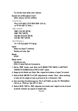

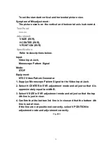


Refer to descriptions below.
Input:
Video Input Jack,
Color Bar signal
Mode:
STOP
Equipment:
NTSC Video Pattern Generator,
Oscilloscope
1. Set to PINP mode, and then move CHILD PICTURE to the upper
left on monitor.
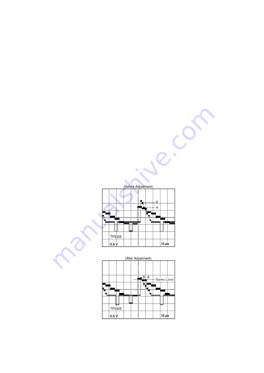
2. Supply a Color Bar signal to the Video Input Jack.
3. Connect the Oscilloscope to TP5305 on the TV PROCESS C.B.A.
4. Select PCONTRAST in EVR adjustment mode and adjust so that
level A and B should be equal in amplitude.
Fig. E13-1
Fig. E13-2
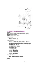
7.4. TEST POINTS AND CONTROL LOCATION
80
Содержание OmniVision PV-C2780-K
Страница 8: ...Fig 1 3 Fig 1 4 8 ...
Страница 26: ...Fig D5 6 1 2 1 Notes in chart 26 ...
Страница 29: ...6 2 2 Inner Parts Location Fig J1 1 29 ...
Страница 30: ...6 2 3 EJECT Position Confirmation Fig J1 2 30 ...
Страница 31: ...6 2 4 Grounding Plate Unit Full Erase Head and Cylinder Unit Fig J2 1 31 ...
Страница 33: ...6 2 5 Capstan Belt Support Angle Intermediate Gear B and Main Cam Gear Fig J3 1 6 2 5 1 Reassembly Notes 33 ...
Страница 44: ...6 3 CASSETTE UP ASS Y SECTION 6 3 1 Top Plate Wiper Arm Unit and Holder Unit Fig K1 1 44 ...
Страница 81: ...81 ...
Страница 85: ...11 2 MECHANISM BOTTOM SECTION 85 ...
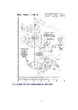
Страница 86: ...11 3 CASSETTE UP COMPARTMENT SECTION 86 ...
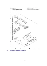
Страница 87: ...11 4 CHASSIS FRAME SECTION 1 87 ...
Страница 88: ...11 5 CHASSIS FRAME SECTION 2 88 ...
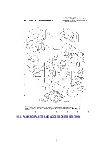
Страница 89: ...11 6 PACKING PARTS AND ACCESSORIES SECTION 89 ...


