


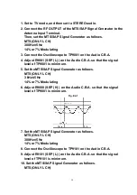


1. Set to TV mode, and then set to STEREO audio.
2. Connect the RF OUTPUT of the MTS/SAP Signal Generator to the
Antenna Input Terminal.
Then, set the MTS/SAP Signal Generator as follows.
MTS (ONLY L CH)
300 Hz±5 Hz
14% or 7% Modulating
3. Connect the Oscilloscope to TP9001 on the Audio C.B.A.
4. Adjust R9001 (SEP (L) ) on the Audio C.B.A. so that the signal
level of TP9001 is minimum.
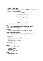
5. Set the MTS/SAP Signal Generator as follows.
MTS (ONLY L CH)
3 kHz±5 Hz
14% or 7% Modulating
6. Adjust R9008 (SEP (H) ) on the Audio C.B.A. so that the signal
level of TP9001 is minimum.
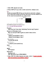
Fig. E2-1
7. Set the MTS/SAP Signal Generator as follows.
MTS (ONLY L CH)
300 Hz±5 Hz
14% or 7% Modulating
8. Connect the Oscilloscope to TP9101 on the Audio C.B.A.
9. Adjust R9101 (SEP (L) ) on the Audio C.B.A. so that the signal
level of TP9101 is minimum.
10. Set the MTS/SAP Signal Generator as follows.
MTS (ONLY L CH)
58
Содержание OmniVision PV-C2780-K
Страница 8: ...Fig 1 3 Fig 1 4 8 ...
Страница 26: ...Fig D5 6 1 2 1 Notes in chart 26 ...
Страница 29: ...6 2 2 Inner Parts Location Fig J1 1 29 ...
Страница 30: ...6 2 3 EJECT Position Confirmation Fig J1 2 30 ...
Страница 31: ...6 2 4 Grounding Plate Unit Full Erase Head and Cylinder Unit Fig J2 1 31 ...
Страница 33: ...6 2 5 Capstan Belt Support Angle Intermediate Gear B and Main Cam Gear Fig J3 1 6 2 5 1 Reassembly Notes 33 ...
Страница 44: ...6 3 CASSETTE UP ASS Y SECTION 6 3 1 Top Plate Wiper Arm Unit and Holder Unit Fig K1 1 44 ...
Страница 81: ...81 ...
Страница 85: ...11 2 MECHANISM BOTTOM SECTION 85 ...
Страница 86: ...11 3 CASSETTE UP COMPARTMENT SECTION 86 ...
Страница 87: ...11 4 CHASSIS FRAME SECTION 1 87 ...
Страница 88: ...11 5 CHASSIS FRAME SECTION 2 88 ...
Страница 89: ...11 6 PACKING PARTS AND ACCESSORIES SECTION 89 ...


