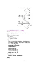
7.3.13. FOCUS, SCREEN, CUT OFF, DRIVE ADJUSTMENT
Purpose:
To set the optimum Focus and Screen.
Symptom of Misadjustment:
The picture is out of Focus and there will be an improper screen
color mix.
Test Point:
TP50 (CRT C.B.A.)
Adjustment:
FOCUS CONTROL (Flyback Transformer),
SCREEN CONTROL (Flyback Transformer),
SUB BRIGHT (EVR),
R- SUB BRIGHT (EVR),
B DRIVE (EVR),
R DRIVE (EVR),
B CUT -OFF (EVR),
G CUT -OFF (EVR),
R CUT -OFF (EVR)
Specification:
Refer to descriptions below.
Input:
Antenna Input Terminal,
Monoscope Pattern Signal
Mode:
STOP
Equipment:
Oscilloscope,
NTSC Video Pattern Generator
1. Set to PINP mode, and then set PARENT PICTURE to UHF/VHF
TUNER/TV DEMODULATOR 2 UNIT input.
2. Supply a Monoscope Pattern Signal to the Antenna Input Terminal.
3. Connect the Oscilloscope to TP50 on the CRT C.B.A.
(Use TP47 for GND.)
68
Содержание OmniVision PV-C2780-K
Страница 8: ...Fig 1 3 Fig 1 4 8 ...
Страница 26: ...Fig D5 6 1 2 1 Notes in chart 26 ...
Страница 29: ...6 2 2 Inner Parts Location Fig J1 1 29 ...
Страница 30: ...6 2 3 EJECT Position Confirmation Fig J1 2 30 ...
Страница 31: ...6 2 4 Grounding Plate Unit Full Erase Head and Cylinder Unit Fig J2 1 31 ...
Страница 33: ...6 2 5 Capstan Belt Support Angle Intermediate Gear B and Main Cam Gear Fig J3 1 6 2 5 1 Reassembly Notes 33 ...
Страница 44: ...6 3 CASSETTE UP ASS Y SECTION 6 3 1 Top Plate Wiper Arm Unit and Holder Unit Fig K1 1 44 ...
Страница 81: ...81 ...
Страница 85: ...11 2 MECHANISM BOTTOM SECTION 85 ...
Страница 86: ...11 3 CASSETTE UP COMPARTMENT SECTION 86 ...
Страница 87: ...11 4 CHASSIS FRAME SECTION 1 87 ...
Страница 88: ...11 5 CHASSIS FRAME SECTION 2 88 ...
Страница 89: ...11 6 PACKING PARTS AND ACCESSORIES SECTION 89 ...


