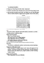


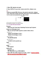


1. Enter EVR adjustment mode.
2. Press DISPLAY key on the remote control for collapse scan.
Note:
Before pressing DISPLAY key on the remote control for collapse
scan, select the desired control function and move the shaded area
to the value for adjustments you will proceed.
Fig. E5-8
7.3.10.1. How to release from Service Mode:
Press DISPLAY key again on the remote control.
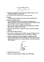
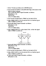
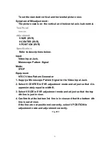
7.3.11. PG SHIFTER ADJUSTMENT
Purpose:
Determine the Video Head Switching Point during Playback.
Symptom of Misadjustment:
May cause Head Switching Noise and/or Vertical Jitter.
Test Point:
TP3001 (TV/VCR Main C.B.A.),
TP6205 (TV/VCR Main C.B.A.)
Adjustment:
PG SHIFTER (EVR)
Specification:
T= 6H±1H (0.38 ms±0.06 ms)
Input:
----------
Mode:
SP Playback
Equipment:
Oscilloscope,
VHS Alignment Tape (VFMS0003H6)
1. Enter EVR PG Shifter Adjustment mode, refer to "
HOW TO ENTER
EVR PG SHIFTER ADJUSTMENT MODE
."
65
Содержание OmniVision PV-C2780-K
Страница 8: ...Fig 1 3 Fig 1 4 8 ...
Страница 26: ...Fig D5 6 1 2 1 Notes in chart 26 ...
Страница 29: ...6 2 2 Inner Parts Location Fig J1 1 29 ...
Страница 30: ...6 2 3 EJECT Position Confirmation Fig J1 2 30 ...
Страница 31: ...6 2 4 Grounding Plate Unit Full Erase Head and Cylinder Unit Fig J2 1 31 ...
Страница 33: ...6 2 5 Capstan Belt Support Angle Intermediate Gear B and Main Cam Gear Fig J3 1 6 2 5 1 Reassembly Notes 33 ...
Страница 44: ...6 3 CASSETTE UP ASS Y SECTION 6 3 1 Top Plate Wiper Arm Unit and Holder Unit Fig K1 1 44 ...
Страница 81: ...81 ...
Страница 85: ...11 2 MECHANISM BOTTOM SECTION 85 ...
Страница 86: ...11 3 CASSETTE UP COMPARTMENT SECTION 86 ...
Страница 87: ...11 4 CHASSIS FRAME SECTION 1 87 ...
Страница 88: ...11 5 CHASSIS FRAME SECTION 2 88 ...
Страница 89: ...11 6 PACKING PARTS AND ACCESSORIES SECTION 89 ...


