


Unit counterclockwise.
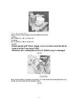
5. Eject the cassette by a10.0 V DC Power Supply again.
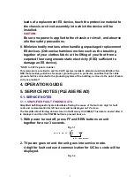
5.1.9. VCR Test Mode
High Voltage is inhibited by connecting Jumper J801 on the TV/VCR Main C.B.A., however, it is
possible to check the VCR even when CRT C.B.A. and Anode Cap are removed.
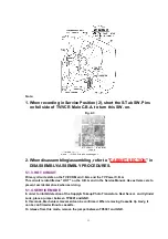
5.1.10. WIRE AND LEAD POSITION DIAGRAM
Fig. 8
5.1.11. DEFEATING THE AUTO TRACKING
To defeat the Auto Tracking Function, place the instrument in the STOP mode and place a
jumper between TP6003 and TP6009 on the TV/VCR Main C.B.A. The tracking will be placed in
the neutral position.
19
Содержание OmniVision PV-C2780-K
Страница 8: ...Fig 1 3 Fig 1 4 8 ...
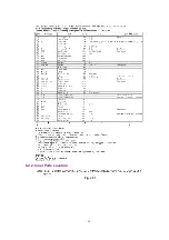
Страница 26: ...Fig D5 6 1 2 1 Notes in chart 26 ...
Страница 29: ...6 2 2 Inner Parts Location Fig J1 1 29 ...
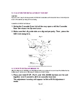
Страница 30: ...6 2 3 EJECT Position Confirmation Fig J1 2 30 ...
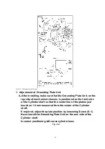
Страница 31: ...6 2 4 Grounding Plate Unit Full Erase Head and Cylinder Unit Fig J2 1 31 ...
Страница 33: ...6 2 5 Capstan Belt Support Angle Intermediate Gear B and Main Cam Gear Fig J3 1 6 2 5 1 Reassembly Notes 33 ...
Страница 44: ...6 3 CASSETTE UP ASS Y SECTION 6 3 1 Top Plate Wiper Arm Unit and Holder Unit Fig K1 1 44 ...
Страница 81: ...81 ...
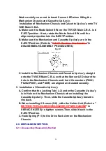
Страница 85: ...11 2 MECHANISM BOTTOM SECTION 85 ...
Страница 86: ...11 3 CASSETTE UP COMPARTMENT SECTION 86 ...
Страница 87: ...11 4 CHASSIS FRAME SECTION 1 87 ...
Страница 88: ...11 5 CHASSIS FRAME SECTION 2 88 ...
Страница 89: ...11 6 PACKING PARTS AND ACCESSORIES SECTION 89 ...


