


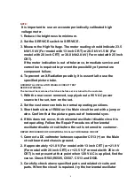


NOTE :
It is important to use an accurate periodically calibrated high
voltage meter.
1. Reduce the brightness to minimum.
2. Set the SERVICE switch to SERVICE .
3. Measure the High Voltage. The meter reading should indicate 23.5
kV±1.5 kV (For model with 13 inch CRT) or 28.5 kV±1.5 kV (For
model with 20 inch CRT) or 30.0 kV±2.0 kV (For model with 25 inch
CRT).
If the meter indication is out of tolerance, immediate service and
correction is required to prevent the possibility of premature
component failure.
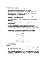
4. To prevent an X-Radiation possibly, it is essential to use the
specified picture tube.
HORIZONTAL OSCILLATOR DISABLE CIRCUIT TEST
SERVICE WARNING :
The test must be made as a final check before set is returned to the customer.
1. With the rear cover removed, supply about a 90 V AC power
source to the set, turn on the set.
2. Set the customer controls to normal operating positions.
3. Short both sides of R804 on the Main circuit board with a jumper
wire. Confirm that the picture goes out of horizontal sync.
4. If this does not occur, the horizontal oscillator disable circuit is
not operating. Follow the Repair Procedures of horizontal
oscillator disable circuit before the set is returned to customer.
REPAIR PROCEDURES OF HORIZONTAL OSCILLATOR DISABLE CIRCUIT
1. Connect a DC voltmeter between capacitor C513 (+) on the Main
circuit board and chassis ground.
2. If approxi21.0 V (For model with 13 inch CRT) or +21.9 V
(For model with 20 inch CRT) or +23.5 V (For model with 25 inch
CRT) is not present at that point when 120 V AC is applied, find the
cause. Check R503,R5505, C5507, C513 and D503.
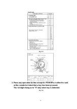
3. Carefully check above specified parts and related circuits and
parts. When the circuit is repaired, try the horizontal oscillator
6
Содержание Omnivision PV-C2542
Страница 22: ...6 1 2 Disassembly Method Fig D2 22 ...
Страница 23: ...Fig D3 23 ...
Страница 24: ...6 1 2 1 Notes in chart 1 Removal of VCR Unit Fig D4 24 ...
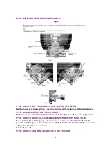
Страница 28: ...6 2 2 Inner Parts Location Fig J1 1 28 ...
Страница 29: ...6 2 3 EJECT Position Confirmation Fig J1 2 29 ...
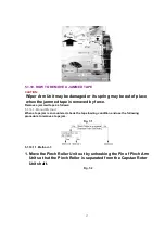
Страница 30: ...6 2 4 Full Erase Head and Cylinder Unit Fig J2 30 ...
Страница 70: ...70 ...
Страница 73: ...11 2 MECHANISM BOTTOM SECTION 73 ...
Страница 74: ...11 3 CASSETTE UP COMPARTMENT SECTION 74 ...
Страница 75: ...11 4 CHASSIS FRAME SECTION 1 75 ...
Страница 76: ...11 5 CHASSIS FRAME SECTION 2 76 ...
Страница 77: ...11 6 PACKING PARTS AND ACCESSORIES SECTION 77 ...
Страница 84: ...121 LSPG1279 PACKING CASE PAPER F 6 84 ...
Страница 97: ...R5317 ERDS2TJ101 CARBON 1 4W 100 97 ...
Страница 99: ...R6045 ERJ6GEYJ102V MGF CHIP 1 10W 1K 99 ...
Страница 118: ...R5401 ERJ6GEYJ561V MGF CHIP 1 10W 560 118 ...
Страница 120: ...R6049 ERJ6GEY0R00V MGF CHIP 1 10W 0 120 ...


