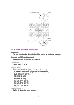
The picture is too dark or too light.
Test Point :
Pin 5 of P6001 (TV/VCR Main C.B.A.) or TP49 (CRT C.B.A.)
Adjustment :
SUB CONTRAST (EVR)
Specification :
3.0 V[p-p]±0.1 V[p-p]
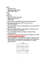
INPUT :
Video Input Jack,
Crosshatch Pattern Signal 1 V[p-p]
(75 terminated)
Mode :
STOP
Equipment :
Oscilloscope,
NTSC Video Pattern Generator
1. Supply a Crosshatch Pattern Signal to the Video Input Jack.
2. Connect the Oscilloscope to Pin 5 of P6001 on the TV/VCR Main
C.B.A. or TP49 on the CRT C.B.A.
3. Select SUB BRIGHT in EVR adjustment mode. Then, after making
a note of the original value, adjust to the (D0).
4. Select SUB CONTRAST in EVR adjustment mode and adjust so
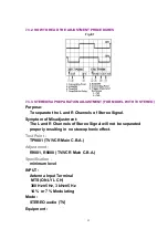
that the level A is 3.0 V[p-p]±0.1 V[p-p].
5. Select SUB BRIGHT in EVR adjustment mode and reset to the
original value.
Fig. E6
59
Содержание Omnivision PV-C2542
Страница 22: ...6 1 2 Disassembly Method Fig D2 22 ...
Страница 23: ...Fig D3 23 ...
Страница 24: ...6 1 2 1 Notes in chart 1 Removal of VCR Unit Fig D4 24 ...
Страница 28: ...6 2 2 Inner Parts Location Fig J1 1 28 ...
Страница 29: ...6 2 3 EJECT Position Confirmation Fig J1 2 29 ...
Страница 30: ...6 2 4 Full Erase Head and Cylinder Unit Fig J2 30 ...
Страница 70: ...70 ...
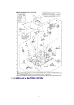
Страница 73: ...11 2 MECHANISM BOTTOM SECTION 73 ...
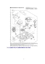
Страница 74: ...11 3 CASSETTE UP COMPARTMENT SECTION 74 ...
Страница 75: ...11 4 CHASSIS FRAME SECTION 1 75 ...
Страница 76: ...11 5 CHASSIS FRAME SECTION 2 76 ...
Страница 77: ...11 6 PACKING PARTS AND ACCESSORIES SECTION 77 ...
Страница 84: ...121 LSPG1279 PACKING CASE PAPER F 6 84 ...
Страница 97: ...R5317 ERDS2TJ101 CARBON 1 4W 100 97 ...
Страница 99: ...R6045 ERJ6GEYJ102V MGF CHIP 1 10W 1K 99 ...
Страница 118: ...R5401 ERJ6GEYJ561V MGF CHIP 1 10W 560 118 ...
Страница 120: ...R6049 ERJ6GEY0R00V MGF CHIP 1 10W 0 120 ...


