


VHS Alignment Tape (VFMS0003H6)
Post Adjustment Driver (VFK0329)
H-Position Adjustment Driver (VFK0330)
7.2.2.2.1. ENVELOPE OUTPUT ADJUSTMENT
The height of the P2 and P3 Posts replacement part is preadjust at the factory.
Purpose:
To achieve a satisfactory picture and secure precise tracking.
Symptom of Misadjustment:
If the envelope is output poorly, much noise will appear in the
picture. Then the tracking will lose precision and the playback
picture will be distorted by any slight variation of the tracking
control circuit.
Equipment Required:
Post Adjustment Driver (VFK0329)
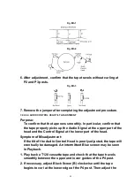
1. Place a jumper between TP6003 and +5 V(TP6009) on the TV/VCR
Main C.B.A. to defeat Auto Tracking.
2. Eject the tape and insert it again to access the Neutral Tracking
position.
3. Play back the alignment tape.
4. Connect the oscilloscope to TP3002 on the Video Signal Process
Section of the TV/VCR Main C.B.A. Use TP6205 as a trigger.
5. Confirm that the RF envelope is flat enough (V1/V-max. is 0.7 or
more). If not, with Post Adjustment Driver, adjust P2 and P3 post
height so that the envelope waveform becomes as flat (V1/V-max.
is 0.7 or more) as possible (Noenvelope drop). If the envelope drop
appears on the left-half of the waveform, adjust P2 post height. If
the envelope drop appears on the right-half of the waveform,
adjust P3 post height.
CAUTION:
Overtightening P2 and P3 posts may cause the threads to strip.
Note:
It will be possible to confirm Step 5 according to following steps.
1. Press the Tracking Control Up or Down button on remote control.
Make sure that the envelope waveform remains flat. If not, readjust
P2 and/or P3 post heights.
47
Содержание Omnivision PV-C2542
Страница 22: ...6 1 2 Disassembly Method Fig D2 22 ...
Страница 23: ...Fig D3 23 ...
Страница 24: ...6 1 2 1 Notes in chart 1 Removal of VCR Unit Fig D4 24 ...
Страница 28: ...6 2 2 Inner Parts Location Fig J1 1 28 ...
Страница 29: ...6 2 3 EJECT Position Confirmation Fig J1 2 29 ...
Страница 30: ...6 2 4 Full Erase Head and Cylinder Unit Fig J2 30 ...
Страница 70: ...70 ...
Страница 73: ...11 2 MECHANISM BOTTOM SECTION 73 ...
Страница 74: ...11 3 CASSETTE UP COMPARTMENT SECTION 74 ...
Страница 75: ...11 4 CHASSIS FRAME SECTION 1 75 ...
Страница 76: ...11 5 CHASSIS FRAME SECTION 2 76 ...
Страница 77: ...11 6 PACKING PARTS AND ACCESSORIES SECTION 77 ...
Страница 84: ...121 LSPG1279 PACKING CASE PAPER F 6 84 ...
Страница 97: ...R5317 ERDS2TJ101 CARBON 1 4W 100 97 ...
Страница 99: ...R6045 ERJ6GEYJ102V MGF CHIP 1 10W 1K 99 ...
Страница 118: ...R5401 ERJ6GEYJ561V MGF CHIP 1 10W 560 118 ...
Страница 120: ...R6049 ERJ6GEY0R00V MGF CHIP 1 10W 0 120 ...


