


No. SX-DSV02310 - 24 -
R2.0 Motor
Business
Division,
Appliances Company, Panasonic Corporation
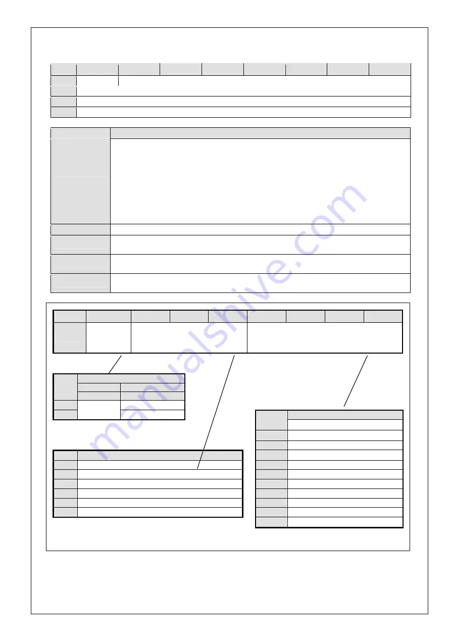
4-2-1 Command code and command argument (Command bytes 1, 4
15)
Byte
bit 7
bit 6
bit 5
bit 4
bit 3
bit 2
bit 1
bit 0
1
0
Command_Code
4–7
Command_Data1
8–11
Command_Data2
12–15
Command_Data3
Title
Description
Command_Code
• Set up the command code.
• Command code is classified into two types as cyclic command code for transmitting real-time data such
as command position and non-cyclic command code for transmitting event-driven data such as parameter
setup.
• Cyclic command code is assigned to bit 6 to 4 in byte 1 of command, and specifies the data for byte 4 to
7.
• Non-cyclic command code is assigned to bit 3 to 0 in byte 1 of command, and specifies the data for byte
8 to 15.
• Use of unsupported cyclic command causes Err. 86.1 RTEX cyclic data error protection 2 alarm.
▪
See the figure below for details.
TMG_CNT
• Use in inter-axis full synchronous mode.
▪
For details, refer to 4-2-1-1.
Command_Data1
• Set up the command data specified by cyclic command code.
▪
For details, refer to the command description (Chapters 5 and 6).
Command_Data2
• Set up the command data specified by non-cyclic command code.
▪
For details, refer to the command description (Chapters 5 and 6).
Command_Data3
• Set up the command data specified by non-cyclic command code.
▪
For details, refer to the command description (Chapters 5 and 6).
Byte
bit 7
bit 6
bit 5
bit 4
bit 3
bit 2
bit 1
bit 0
1
TMG_CNT/
CMD_Error
Cyclic command code
(Specify data of Bytes 4–7.)
Non-cyclic command code
(Specify data of Bytes 8–15.)
Application
Command
Response
bit 7
TMG_CNT
CMD_Error
0 Command
normal
Non-cyclic command
1
See 4-2-1-1.
Command error
bit 3–0
Application
0 Normal
command
1 Reset
command
Cyclic command
2
System ID command
bit 6–4
Application
3 Reserved
0 NOP
4
Return to home command
1
Profile position control mode (PP)
5 Alarm
command
2 Cyclic
position
control mode (CP)
6 Parameter
command
3
Cyclic velocity control mode (CV)
7 Profile
command
4
Cyclic thrust control mode (CT)
8–9 Reserved
5–7 Reserved
10 Monitor
command
11–15 Reserved
Set the cyclic command code to NOP (bits 6
4:0) only when transmitting invalid data after canceling the reset, and
specify the control mode to be used (PP, CP, CV or CT). Do not transmit NOP.
For details of each command, refer to Chapters 5 and 6.


