−
B45
−
−
B44
−
English
This driver is equipped with a dynamic brake for emergency stop.
Pay a special attention to the followings.
Caution
1.Dynamic brake is only for emergency stop.
Do not start/stop the motor by turning on/off the Servo-ON
signal (SRV-ON).
Otherwise it may damage the dynamic brake circuit of the
driver.
The Motor becomes a dynamo when driven externally and
short circuit current occurred while dynamic brake is activat-
ed may cause smoking or fire.
2. Dynamic brake is a short-duration rating, and designed for only
emergency stop. Allow approx. 10 minutes pause when the dynamic
brake is activated during high-speed running.
(F-frame (200 V) built-in dynamic brake resistor is capable of han-
dling up to 3 continuous halts at the rated revolutions with max.
permissible inertia. When overheated under more critical operating
conditions, the brake will blow out and should be replaced with a
new one.)
• You can activate the dynamic brake in the following cases.
1) when the main power is turned off
2) at Servo-OFF
3) when one of the protective function is activated.
4) when over-travel inhibit input (NOT, POT) of connector X4 is acti-
vated
In the above cases from 1) to 4), you can select either activation of
the dynamic brake or making the motor free-run during decelera-
tion or after the stop, with parameter.
9. Dynamic Brake
Outline
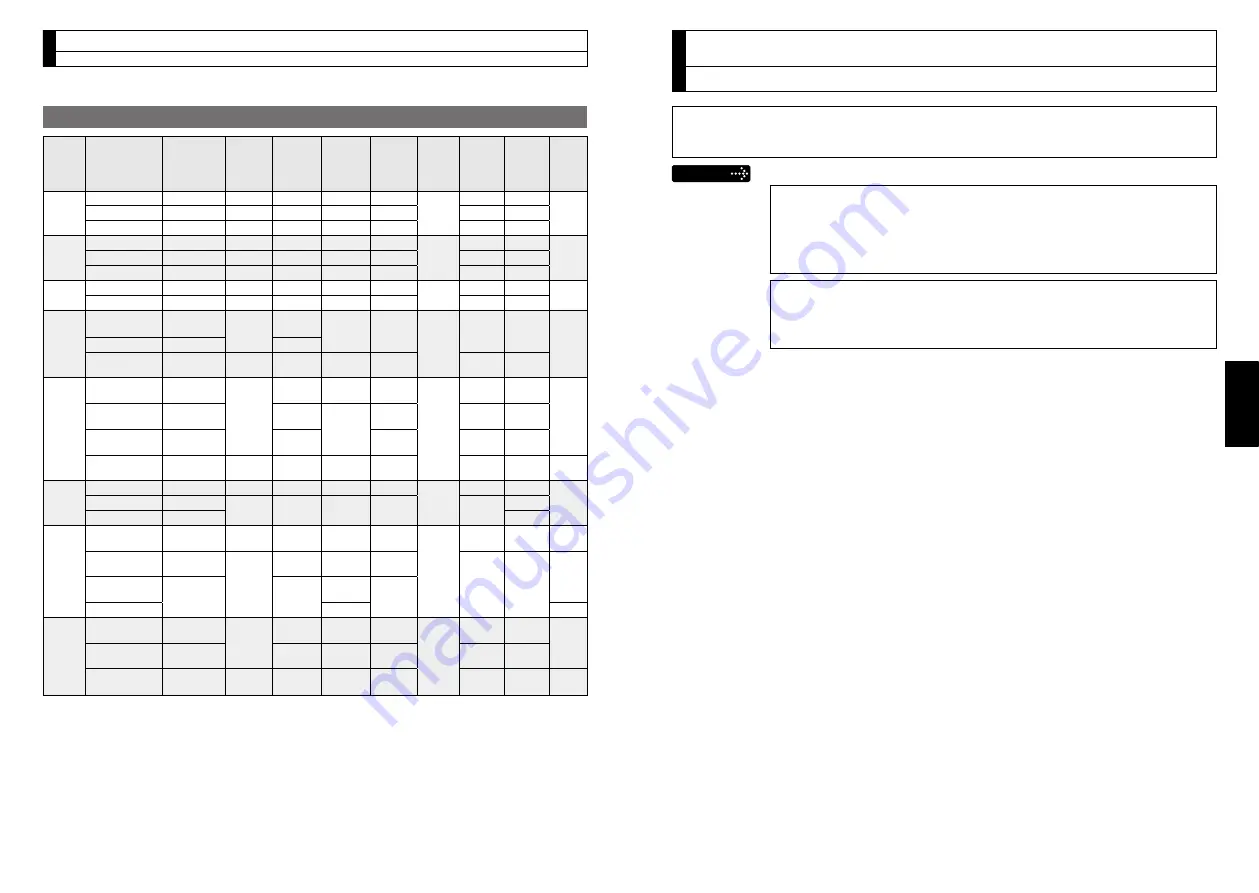
Specifications of Built-in Holding Brake
Motor
series
Motor
output
Static
friction
torque
N·m
Rotor
inertia
×10
–4
kg·m
2
Engaging
time
ms
Releasing
time
ms
Exciting
current
DC A
(at cool-off)
Releasing
voltage
Permissible
work (J) per
one braking
Permissible
total work
x 10
3
J
Permissible
angular
acceleration
rad/s
2
MSME
50 W, 100 W 0.29 or more 0.002 35 or less 20 or less
0.3
DC1 V
or more
39.2
4.9
30000
200 W, 400 W 1.27 or more 0.018 50 or less 15 or less 0.36
137
44.1
750 W
2.45 or more 0.075 70 or less 20 or less 0.42
196
147
MSMD
50 W, 100 W 0.29 or more 0.002 35 or less 20 or less
0.3
DC1 V
or more
39.2
4.9
30000
200 W, 400 W 1.27 or more 0.018 50 or less 15 or less 0.36
137
44.1
750 W
2.45 or more 0.075 70 or less 20 or less 0.42
196
147
MHMD 200 W, 400 W 1.27 or more 0.018 50 or less 15 or less 0.36
DC1 V
or more
137
44.1 30000
750 W
2.45 or more 0.075 70 or less 20 or less 0.42
196
147
MSME
1.0 kW, 1.5 kW,
2.0 kW
7.8 or more
0.33 50 or less 15 or less
(100)
0.81
DC2 V
or more
392
490
10000
3.0 kW
11.8 or more
80 or less
4.0 kW, 5.0 kW 16.2 or more
1.35
110 or
less
50 or less
(130)
0.9
1470
2200
MDME
1.0 kW
4.9 or more
1.35
80 or less 70 or less
(200)
0.59
DC2 V
or more
588
780
10000
1.5 kW, 2.0 kW 13.7 or more
100 or
less
50 or less
(130)
0.79
1176
1500
3.0 kW
16.2 or more
110 or
less
0.9
1470
2200
4.0 kW, 5.0 kW 24.5 or more
4.7
80 or less 25 or less
(200)
1.3
1372
2900
5440
MFME
1.5 kW
7.8 or more
4.7
80 or less 35 or less 0.83
DC2 V
or more
1372
2900
10000
2.5 kW
21.6 or more
8.75
150 or
less
100 or
less
0.75
1470
1500
4.5 kW
31.4 or more
2200
MGME
900 W
13.7 or more
1.35
100 or
less
50 or less
(130)
0.79
DC2 V
or more
1176
1500 10000
2.0 kW
24.5 or more
4.7
80 or less 25 or less
(200)
1.3
1372
2900
5440
3.0 kW
58.8 or more
150 or
less
50 or less
(130)
1.4
4.5 kW
50 or less
5000
MHME
1.0 kW
4.9 or more
1.35
80 or less 70 or less
(200)
0.59
DC2 V
or more
588
780
10000
1.5 kW
13.7 or more
100 or
less
50 or less
(130)
0.79
1176
1500
2.0 kW to
5.0 kW
24.5 or more
4.7
80 or less 25 or less
(200)
1.3
1372
2900
5440
• Excitation voltage is DC24 V ±10 %.
• Releasing time values represent the ones with DC-cutoff using a varistor.
Values in ( ) represent those measured by using a diode (V03C by Hitachi, Ltd.)
• Above values (except static friction torque, releasing voltage and excitation current) rep-
resent typical values.
• Backlash of the built-in holding brake is kept ±1˚or smaller at ex-factory point.
• Service life of the number of acceleration/deceleration with the above permissible an-
gular acceleration is more than 10 million times. (Life end is defined as when the brake
backlash drastically changes.)
8. Built-in Holding Brake
Outline / Specifications


