background image

4

Instructions to customer 

Important information (for Australian users)

Installation

Attached to this apparatus is an approval label. This label is evidence that it is a “Permitted Attachment” 
which has been authorised to be connected to your telephone service.
Conditions relating to connection and operation of this Permitted Attachment are contained in
Telecommunications General By-Law 220 (5).

You are authorised to install this Permitted Attachment yourself by plugging it into the line socket of any
regular telephone. You may connect it in place of your existing telephone or to any spare telephone 
socket installed in your premises.

To disconnect your existing telephone you must first remove its plug from the line socket. You can then
insert the plug of your Permitted Attachment into the socket and use your equipment.

If the plug of your existing telephone cannot be readily removed, you will have to remove the screw 
securing it. To do this proceed as follows:

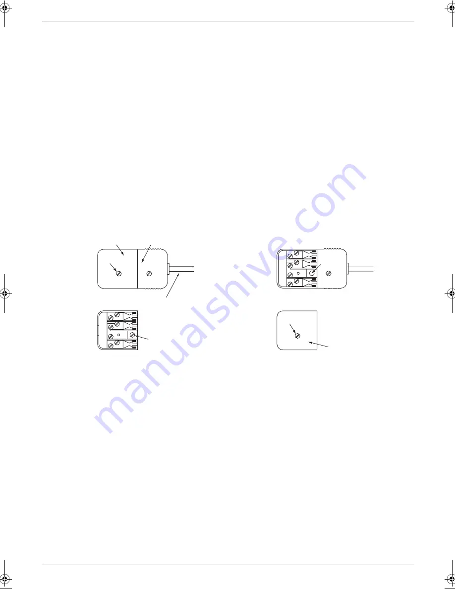
1. Loosen screw “A” sufficiently to remove the socket cover. (See Fig. 1.)
2. Remove screw “B” and withdraw the plug. (See Fig. 2.)
3. Replace screw “B”. (See Fig. 3.) Ensure that it screws completely into the socket recess. (If the screw 

is too long, increase the hole depth or replace the screw with one 5 mm shorter.)

4. Replace socket cover and tighten screw “A”. (See Fig. 4.)

If you are satisfied with the operation of your telephone service after plugging in your Permitted 
Attachment, your installation is completed.

You will be unable to connect this Permitted Attachment if your telephone service consists only of a wall
phone or an old style telephone which is not connected by means of a modern plug and socket. In such
cases a new socket will need to be installed.

Should the Permitted Attachment not operate when plugged into a socket, it is either faulty or unsuitable 
for operation with your telephone service. It should be returned to the store where purchased.

Service difficulties

If at any time a fault occurs on your telephone service carry out the following checks before you call for
service:

L

 Disconnect the Permitted Attachment and try using the service with the normal telephone.

L

 If the telephone service then operates satisfactorily, the fault is in your Permitted Attachment. Leave 

the Permitted Attachment disconnected and report the fault to its supplier or agent to arrange for 
repair.

L

 If when using the telephone the service is still faulty, report the fault to “Service Difficulties and Faults” 

for attention.

You are required to keep this Permitted Attachment in good working order while it is connected to your
telephone service. Its construction or internal circuit must not be modified in any way without permission.

SOCKET

SCREW “A”

PLUG

Fig. 1

TELEPHONE CORD

Connect to the PLUG
as shown in Fig. 1.

(                                    )

SCREW
“B”

Fig. 2

SCREW
“B”

Fig. 3

SOCKET

SCREW “A”

Fig. 4

MC6040_6260CX-PNQW1377ZA-QRG-en.book  Page 4  Wednesday, July 30, 2008  10:24 AM

Содержание KX-MC6040 - Color Laser Multi-Function...

Страница 1: ...d model is KX MC6040 Be sure to use the USB cable supplied with this unit L This unit is compatible with Caller ID You must subscribe to the appropriate service offered by your service provider teleph...

Страница 2: ...cts of the product life cycle from product development to energy saving designs from greater product reusability to waste conscious packaging practices Note L The suffix in the model number will be om...

Страница 3: ...IRST NO 111 OR OTHER CALLS CAN BE MADE FROM THIS DEVICE DURING A MAINS POWER FAILURE IMPORTANT NOTICE Under power failure conditions this telephone may not operate Please ensure that a separate teleph...

Страница 4: ...ee Fig 4 If you are satisfied with the operation of your telephone service after plugging in your Permitted Attachment your installation is completed You will be unable to connect this Permitted Attac...

Страница 5: ...unit If you are not sure of the type of power supplied to your home consult your dealer or local power company For safety purposes this unit is equipped with a grounded plug If you do not have this ty...

Страница 6: ...ll jack and do not use Unplug this unit from power outlets and refer servicing to an authorised service centre when any of the following conditions occur L If the power cord is damaged or frayed L If...

Страница 7: ...to report a gas leak when in the vicinity of the leak SAVE THESE INSTRUCTIONS CLASS 1 LASER PRODUCT The printer of this unit utilises a laser Use of controls or adjustments or performance of procedure...

Страница 8: ...or imprisonment may be imposed on those found guilty The following are examples of items that may be illegal to copy in your country Currency Bank notes and checks Bank and government bonds and securi...

Страница 9: ...ries 2 Preparation L Main settings prior to activating the unit such as Multi function software information 3 Printer L More ways to use the printer such as printing on special media 4 Scanner L More...

Страница 10: ...volume 14 Initial Programming 1 9 Date and time 14 1 10 Your logo 14 1 11 Your fax number 14 1 12 Configuring the unit to access the LAN 14 1 13 Installing Multi Function Station 15 2 How to Use Prin...

Страница 11: ...t take care of the power plug cap and or packing materials appropriately L Do not remove the drum cartridges and toner cartridges from the unit when repacking the unit for shipping and transportation...

Страница 12: ...nit L Do not extend the telephone line cord 1 The power cord or telephone line cord may differ slightly Use the appropriate power cord or telephone line cord for where you use the unit Note L If any o...

Страница 13: ...select the desired setting 1 Pulse For rotary pulse dial service 2 Tone default For tone dial service 4 Set 5 Press Menu to exit 1 6 Selecting the operation mode Scan Copy Fax Print KX MC6260 only You...

Страница 14: ...y to select 12 hour time entry or 24 hour time entry L If you selected 12 hour time entry press V or repeatedly to select AM or PM Example 10 August 2008 10 15 PM 12 hour clock format 1 Press V or rep...

Страница 15: ...ulti Function Station 2 Insert the supplied CD ROM into your CD ROM drive 3 Easy Installation L The installation will start automatically 4 When the setup program starts follow the on screen instructi...

Страница 16: ...ation i Scan 3 Click the desired application icon Copy 2 4 Making a copy 2 4 1 Using the scanner glass 1 If the Copy light is OFF turn it ON by pressing Copy 2 Set the original page 13 3 If necessary...

Страница 17: ...enu 2 Press V or repeatedly to select Print Report 3 Press or repeatedly to select Colour Test 4 Press Set to start printing i Menu Colour test The unit will print a colour test page consisting of bla...

Страница 18: ...ge Supplies Waste Toner Full L The waste toner cartridge life is near its end Replace the waste toner cartridge as soon as possible Check Document L The document was not fed into the unit properly Rem...

Страница 19: ...The unit has a document in memory See the other displayed message instructions to print out the document L If feature 442 is set to Always check the connection between the computer and the unit check...

Страница 20: ...se a supported SD card Out of Paper Input Tray 1 L Recording paper is not installed or the paper input tray has run out of paper Install paper L Recording paper was not fed into the unit properly Rein...

Страница 21: ...tion Error L There is something wrong with the scanner position Turn the power switch OFF then ON If the problem cannot be solved contact our service personnel SD Card is pulled out L The SD card has...

Страница 22: ...22 Notes...

Страница 23: ...23 Notes...

Страница 24: ...sonic New Zealand Limited Panasonic Australia Pty Limited Austlink Corporate Park 1 Garigal Road Belrose NSW 2085 Australia Sales Department Note for Australian users Panasonic Australia operates a to...

Отзывы: