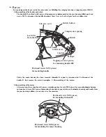
11.3. ANALOG BOARD (PCB2) : COMPONENT VIEW
A B C 1
2
3
4
5
6
7
8
9
A B C
a
b
c
d
A B C D E F G
R25
PC5
C15
R11
C20
R2
R1
C1
R26
C63
Q4
R10
C12
PC4
PC1
PC2
C8
C2
R3
R81
C27
R36
R80
R35
C25
C64
R33
C62
C56
R51
R4
R19
R18
R9
J3
1
17
Q3
R75
1
4
5
8
IC1
C43
C45
R73
R72
R45
L8
L7 L5
L6
R63
R62
R49
R66
R65
R53
R55
R67
C50
R64
C49
C55
R34
C24
R41
C31
C23
R38
R39
R54
C22
C21
C26
C32
R42
C33
R52
R50
C57
C65
R46
C53
R48
C52
C51
R47
C54
Q2
Q11
C46
CN3
C40
C41
R74
R23
R22
L1
L2
L12
D1
L3
L4
CN5
CN4
L11
Q6
R24
+24V
+5VD
AG
DG
+5V
A
IC2
5
8
1
4
PFUP1268ZA
ANALOG BOARD (COMPONENT)
KX-FT72BR-G
KX-
FT72B
R
-G
153
Содержание KX-FT72BR-G
Страница 3: ...1 1 LCD MESSAGE 1 INTRODUCTION 3 KX FT72BR G ...
Страница 8: ...1 11 TEST CHART 1 11 1 ITU T NO 1 TEST CHART 8 KX FT72BR G ...
Страница 9: ...1 11 2 CCITT NO 2 TEST CHART 9 KX FT72BR G ...
Страница 10: ...1 12 LOCATION OF CONTROLS 1 12 1 OVERVIEW 10 KX FT72BR G ...
Страница 28: ...2 3 4 2 DOCUMENT JAM CROSS REFERENCE SENSOR SECTION P 72 DISASSEMBLY INSTRUCTIONS P 84 28 KX FT72BR G ...
Страница 29: ...2 3 4 3 MULTIPLE FEED CROSS REFERENCE DISASSEMBLY INSTRUCTIONS P 84 29 KX FT72BR G ...
Страница 30: ...2 3 4 4 SKEW CROSS REFERENCE DISASSEMBLY INSTRUCTIONS P 84 30 KX FT72BR G ...
Страница 34: ...CROSS REFERENCE DISASSEMBLY INSTRUCTIONS P 84 34 KX FT72BR G ...
Страница 37: ...2 3 5 1 2 SOMETIMES THERE IS A TRANSMIT PROBLEM CROSS REFERENCE LCD MESSAGE P 3 37 KX FT72BR G ...
Страница 39: ...2 3 5 1 4 THE UNIT CAN COPY BUT CANNOT TRANSMIT RECEIVE 39 KX FT72BR G ...
Страница 45: ...45 KX FT72BR G ...
Страница 46: ...CROSS REFERENCE TEST FUNCTIONS P 82 46 KX FT72BR G ...
Страница 47: ...CROSS REFERENCE TEST FUNCTIONS P 82 47 KX FT72BR G ...
Страница 48: ...48 KX FT72BR G ...
Страница 49: ...CROSS REFERENCE TEST FUNCTIONS P 82 CROSS REFERENCE TEST FUNCTIONS P 82 49 KX FT72BR G ...
Страница 50: ...50 KX FT72BR G ...
Страница 51: ...51 KX FT72BR G ...
Страница 52: ...CROSS REFERENCE TEST FUNCTIONS P 82 52 KX FT72BR G ...
Страница 58: ...58 KX FT72BR G ...
Страница 59: ...Normal Wave Patterns 59 KX FT72BR G ...
Страница 61: ...CROSS REFERENCE NG EXAMPLE P 63 CHECK THE STATUS OF THE DIGITAL BOARD P 64 61 KX FT72BR G ...
Страница 62: ...CROSS REFERENCE CHECK THE STATUS OF THE DIGITAL BOARD P 64 62 KX FT72BR G ...
Страница 63: ...2 3 6 2 NG EXAMPLE 63 KX FT72BR G ...
Страница 66: ...2 3 7 2 DEFECTIVE ITS INTEGRATED TELEPHONE SYSTEM SECTION 66 KX FT72BR G ...
Страница 68: ...2 Troubleshooting Flow Chart 68 KX FT72BR G ...
Страница 69: ...69 KX FT72BR G ...
Страница 73: ...2 3 11 READ SECTION Refer to SCANNING BLOCK P 112 73 KX FT72BR G ...
Страница 79: ...2 4 5 SERVICE MODE SETTINGS Example of a printed out list 79 KX FT72BR G ...
Страница 84: ...3 DISASSEMBLY INSTRUCTIONS 3 1 HOW TO REMOVE THE HANDSET CRADLE CABINET HOOK BUTTON AND SPEAKER 84 KX FT72BR G ...
Страница 85: ...3 2 HOW TO REMOVE THE OPERATION BLOCK 85 KX FT72BR G ...
Страница 86: ...3 3 HOW TO REMOVE THE OPERATION BOARD AND LCD 86 KX FT72BR G ...
Страница 87: ...3 4 HOW TO REMOVE THE BOTTOM FRAME AND ANALOG BOARD 87 KX FT72BR G ...
Страница 88: ...3 5 HOW TO REMOVE THE DIGITAL POWER SUPPLY BOARD AND AC INLET 88 KX FT72BR G ...
Страница 89: ...3 6 HOW TO REMOVE THE MOTOR BLOCK AND SEPARATION ROLLER 89 KX FT72BR G ...
Страница 90: ...3 7 HOW TO REMOVE THE MOTOR AND GEARS OF MOTOR BLOCK 90 KX FT72BR G ...
Страница 91: ...3 8 HOW TO REMOVE THE IMAGE SENSOR CIS 91 KX FT72BR G ...
Страница 92: ...3 9 HOW TO REMOVE THE DOCUMENT FEED ROLLER 92 KX FT72BR G ...
Страница 93: ...3 10 HOW TO REMOVE THE THERMAL HEAD 93 KX FT72BR G ...
Страница 94: ...3 11 INSTALLATION POSITION OF THE LEAD WIRES 94 KX FT72BR G ...
Страница 96: ...4 3 FLAT PACKAGE IC INSTALLATION PROCEDURE 4 4 BRIDGE MODIFICATION PROCEDURE 96 KX FT72BR G ...
Страница 97: ...5 CIRCUIT OPERATIONS 5 1 CONNECTION DIAGRAM 97 KX FT72BR G ...
Страница 99: ...5 2 1 General Block Diagram 99 KX FT72BR G ...
Страница 109: ...5 4 2 BLOCK DIAGRAM 109 KX FT72BR G ...
Страница 111: ...111 KX FT72BR G ...
Страница 117: ...5 4 6 3 4 COPYING CROSS REFERENCE SENSOR SECTION P 72 117 KX FT72BR G ...
Страница 126: ...b Redundancy Compression Process Coding Mode This unit uses one dimensional MH format 126 KX FT72BR G ...
Страница 132: ...5 10 1 CIRCUIT DIAGRAM 132 KX FT72BR G ...
Страница 135: ...5 12 POWER SUPPLY BOARD SECTION 135 KX FT72BR G ...
Страница 137: ...6 TERMINAL GUIDE OF THE ICs TRANSISTORS AND DIODES 137 KX FT72BR G ...
Страница 138: ...7 FIXTURES AND TOOLS 138 KX FT72BR G ...
Страница 139: ...8 CABINET MECHANICAL AND ELECTRICAL PARTS LOCATION 8 1 OPERATION PANEL SECTION 139 KX FT72BR G ...
Страница 140: ...8 2 UPPER CABINET SECTION 140 KX FT72BR G ...
Страница 141: ...8 3 LOWER CABINET P C B SECTION CROSS REFFERENCE MOTOR SECTION P 142 141 KX FT72BR G ...
Страница 142: ...8 4 MOTOR SECTION 142 KX FT72BR G ...
Страница 143: ...8 5 ACTUAL SIZE OF SCREWS 143 KX FT72BR G ...
Страница 144: ...9 ACCESSORIES AND PACKING MATERIALS 144 KX FT72BR G ...
Страница 163: ...163 KX FT72BR G Y M KXFT72BRG ...