20.3. Telephone Line Interface
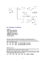
<Function>
- Bell signal detection
- Clip signal detection
- ON/OFF hook circuit
- Metering Pulse circuit
- Audio circuits
Bell & Clip (: Calling Line Identification Presentation: Caller ID) signal detection:
In the standby mode, Q2 is open to cut the DC loop current and decrease the ring load.
When ring voltage appears at the TP3 (A) and TP40 (B) leads (when the telephone rings), the
signal is transferred as follows;
- A C4 R2 R29 IC2 (DLP) [BELL & CLIP]
- B C3 R1 R30 IC2 (DLP) [BELL & CLIP]
ON/OFF hook circuit:
In the standby mode, Q2 is open, and connected as to cut the DC loop current and to cut the
voice signal. The unit is consequently in an off-hook condition.
When IC2 detects a ring signal or press the TALK Key onto the handset, Q3 turns on and then
Q2 turns on, thus providing an off-hook condition (active DC current flow through the circuit)
and the following signal flow is for the loop current.
- A R77 D2 Q2 R8 Q3 D2 B [OFF HOOK]
49
Содержание KX-A140EXC
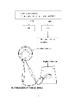
Страница 46: ...18 FREQUENCY TABLE MHz 46 ...
Страница 52: ...24 CPU DATA BASE UNIT 24 1 IC2 BBIC 52 ...
Страница 56: ...45 MICP A I 56 ...
Страница 60: ...60 ...
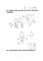
Страница 61: ...28 CABINET AND ELECTRICAL PARTS LOCATION HANDSET 29 ACCESSORIES AND PACKING MATERIALS 61 ...
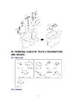
Страница 62: ...30 TERMINAL GUIDE OF THE ICs TRANSISTORS AND DIODES 30 1 Base Unit 30 2 Handset 62 ...
Страница 91: ...4 1 5 8 PbF 1 28 18 IC3 IC2 IC1 11 64 1 16 17 32 49 48 33 Marked ...
Страница 93: ...Marked PbF IC1 IC2 100 80 5 8 4 1 50 51 30 31 1 11 18 1 28 IC3 ...
Страница 94: ...Marked 1 PROG PbF BOOK UP POWER CAN DOWN RIGHT REDIAL LEFT 1 2 3 6 5 7 0 R 4 9 8 INT MIC TALK 36 CN2 ...
Страница 95: ...Clip Base PCB G N D S D A S C L ...


