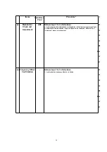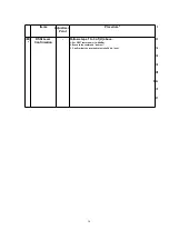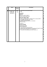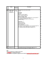
14.2. Adjustment Standard (Base Unit)
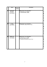
When connecting the Simulator Equipments for checking, please refer to below.
14.2.1. Component View
Note:
(H) - (O) is refered to
ADJUSTMENTS (BASE UNIT)
()
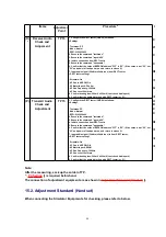
14.2.2. Flow Solder Side View
Note:
(A) - (P) is refered to
ADJUSTMENTS (BASE UNIT)
()
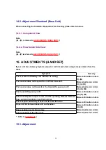
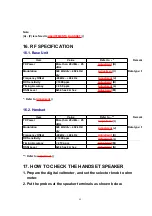
15. ADJUSTMENTS (HANDSET)
If your unit have below symptoms, adjust or confirm each item using remedy column from the
table.
Symptom
Remedy
The movement of Battery Low indicator is wrong.
Make confirmation in item
(F)~(G)
The handset does not respond to a call from base unit.
Make adjustments in item
(H), (J)~(N)
The handset does not transmit or the transmit frequency is off.
Make adjustments in item
(H)~(K), (M)
The transmit frequency is off.
Make confirmation in item
(H)~(K), (M)
The transmit power output is low, and the operating distance between
base unit and handset is less than normal.
Make confirmation in item
The reception sensitivity of base unit is low with noise.
Make confirmation in item
Dose not link between base unit and handset.
Make confirmation in item
(H)~(N)
The reception level is high or low.
Make adjustments in item
The transmit level is high or low.
Make adjustments in item
* : Refer to
Adjustment
()
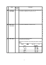
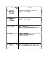
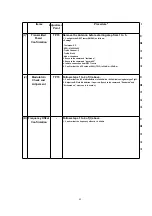
15.1. Adjustment
39
Содержание KX-A140EXC
Страница 46: ...18 FREQUENCY TABLE MHz 46 ...
Страница 52: ...24 CPU DATA BASE UNIT 24 1 IC2 BBIC 52 ...
Страница 56: ...45 MICP A I 56 ...
Страница 60: ...60 ...
Страница 61: ...28 CABINET AND ELECTRICAL PARTS LOCATION HANDSET 29 ACCESSORIES AND PACKING MATERIALS 61 ...
Страница 62: ...30 TERMINAL GUIDE OF THE ICs TRANSISTORS AND DIODES 30 1 Base Unit 30 2 Handset 62 ...
Страница 91: ...4 1 5 8 PbF 1 28 18 IC3 IC2 IC1 11 64 1 16 17 32 49 48 33 Marked ...
Страница 93: ...Marked PbF IC1 IC2 100 80 5 8 4 1 50 51 30 31 1 11 18 1 28 IC3 ...
Страница 94: ...Marked 1 PROG PbF BOOK UP POWER CAN DOWN RIGHT REDIAL LEFT 1 2 3 6 5 7 0 R 4 9 8 INT MIC TALK 36 CN2 ...
Страница 95: ...Clip Base PCB G N D S D A S C L ...

