50
9.3.7.
Adjustment
Item
Operation
Default
Remarks
Shading
1. Click
“Adjust”
on the main menu.
2. Click
“Shading”
on the Adjust menu.
3. Set the resolution (300 dpi and/or 600 dpi).
4. Clean the conveyor, rollers, and scanning glass section
according to the message on the display.
Then click
“OK”
.
5. Set the Shading Sheet (Part No.: See.
Feed Tray in portrait orientation.
6. Click
“OK”
to start the shading correction.
7. Confirm the result.
8. Click
“OK”
to return to the Adjust menu.
—
Until this process is
completed, don’t stop the
process by opening any
doors or turning off the
scanner.
All Position
1. Click
“Adjust”
on the main menu.
2. Set 2 pcs of Test Chart A4 (Part No.: See.
(
)) on the
Feed Tray in portrait orientation.
3. Click
“All position”
on the Adjust menu to execute scanning
position and length adjustment.
4. Check the result.
5. Click
“OK”
to return to the Adjust menu.
—
Set 2 pcs of Test Chart A4 on
the Feed Tray in the
following order:
1st page: Front side
(Face-down)
2nd page: Back side
(Face-up)
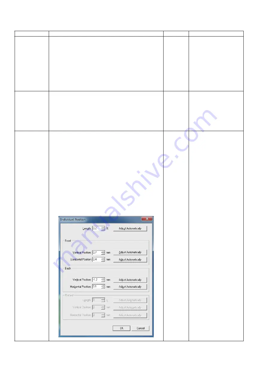
Individual Position 1. Click
“Adjust”
on the main menu.
2. Adjust Automatically.
a. Set Test Chart A4 (Part No.: See.
(
)) on the Feed
Tray in portrait orientation.
b. Click
“Individual Position”
on the Adjust menu.
c. Click one of 5
“Adjust Automatically”
buttons to execute
the adjustment.
d. Check the result.
e. Click
“OK”
to finish the adjustment.
f. Click
“OK”
to return to the Adjust menu.
3. Adjust Manually.
a. Click
“Individual Position”
on the Adjust menu.
b. Change the parameters (mm, %) as required.
(Refer to Remarks.)
c. Click
“OK”
to renew the setting, and to return to the
Adjust menu.
—
1. Adjust Automatically
(5 adjustments)
Set face-down
Length
Front V. Position
Front H. Position
Set face-up
Back V. Position
Back H. Position
2. Adjust Manually
(Length)
+: Increasing the number
makes the scanning
document length shorter.
(Vertical Position)
+: Increasing the number
makes the document
scanning position shifted
upward.
(Horizontal Position)
+: Increasing the number
makes the document
scanning position shifted
to the left.
Note:
If the appropriate
scanning position can
not be obtained by any
of the manual
adjustments, check the
CIS installation.
Содержание KV-S1027C
Страница 7: ...7 ...
Страница 9: ...9 3 Location of Controls and Components 3 1 Main Unit ...
Страница 10: ...10 ...
Страница 16: ...16 5 Section Views 5 1 Motor 5 2 Roller ...
Страница 17: ...17 5 3 Board and Sensor ...
Страница 31: ...31 7 3 8 Wiring of Upper Chassis ...
Страница 128: ...128 14 Exploded View and Replacement Parts List ...
Страница 133: ...133 14 3 Feed Tray Assembly 302 305 302 303 307 301 306 305 302 304 Feed Tray Assembly ...
Страница 180: ...180 15 Appendix The extract from an Operating Manual N K KVS1057C KVS1027C KVSL1066 KVSL1056 KVSL1055 KVSL1036 KVSL1035 ...
Страница 188: ...Index 74 8 Operating Manual Table of Contents ...
Страница 255: ...PNQX6995ZA DD0914HS0 Panasonic System Networks Co Ltd 2014 ...


