


8
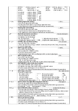
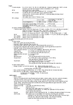
JPt100
–199.9 to 500.0 :
JPt100
–199.9 to 900.0 :
Pt100
–200 to 850
:
Pt100
–300 to 1500 :
JPt100
–200 to 500
:
JPt100
–300 to 900
:
4 to 20mA
–1999 to 9999:
0 to 20mA
–1999 to 9999:
0 to 1V
–1999 to 9999:
0 to 5V
–1999 to 9999:
1 to 5V
–1999 to 9999:
0 to 10V
–1999 to 9999:
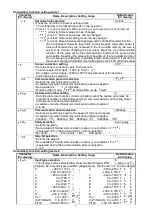
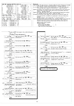
Scaling high limit setting
1370
• Sets the scaling high limit value.
• Scaling low limit value to input range high limit value
(The placement of the decimal point follows the selection.)
Scaling low limit setting
–200
• Sets the scaling low limit value.
• Input range low limit value to scaling high limit value
(The placement of the decimal point follows the selection.)
Decimal point place selection
No decimal point
• Selects decimal point place.
• Available only for DC input.
• No decimal point:
1 digit after decimal point:
2 digits after decimal point:
3 digits after decimal point:
PV filter time constant setting
0.0 seconds
• Sets PV filter time constant.
(If the set value is too large, it affects control result due to the delay of response)
• 0.0 to 10.0 seconds
OUT high limit setting
100%
• Sets OUT high limit value.
• Not available for ON/OFF action.
• OUT low limit value to 105%
(Setting higher than 100% is effective to DC current output type)
OUT low limit setting
0%
• Sets OUT low limit value.
• Not available for ON/OFF action.
• –5% to OUT high limit value
(Setting less than 0% is effective to DC current output type)
OUT ON/OFF action hysteresis setting
1.0
• Sets OUT ON/OFF action Hysteresis.
• Available only when the control action is ON/OFF action
• Thermocouple, RTD input: 0.1 to 100.0 ( )
DC input: 1 to 1000 (The placement of the decimal point follows the selection)
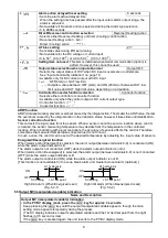
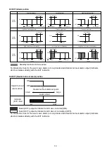
Alarm type selection
No alarm action
• Selects an alarm type.
No alarm action
:
Process high alarm
:
High limit alarm
:
Process low alarm
:
Low limit alarm
:
High limit alarm with standby
:
High/Low limits alarm
:
Low limit alarm with standby
:
High/Low limit range alarm:
High/Low limits alarm w/standby:
Alarm action Energized/Deenergized selection
Energized
• Selects the alarm action Energized/Deenergized.
• Not available if No alarm action is selected during the Alarm type selection.
• Energized:
Deenergized:
Alarm HOLD function selection
Alarm Not Holding
• Selects either [Holding] or [Not Holding] of alarm HOLD function.
If alarm HOLD function is set to [Holding], once the alarm functions, alarm output
remains until the power is turned off.
• Not available if No alarm action is selected during the Alarm type selection
• Alarm Not Holding:
Alarm Holding:
Alarm hysteresis setting
1.0
• Sets the alarm hysteresis.
• Not available if No alarm action is selected during the Alarm type selection
• Thermocouple, RTD input: 0.1 to 100.0 ( )
DC input: 1 to 1000 (The placement of the decimal point follows the selection)


