


11
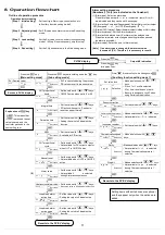
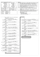
8. Operation flowchart
Outline of operation procedure
Operation before running
[Step 1 Initial setting]
: Set Input type, Alarm type, control action, etc.
in Auxiliary function setting mode 2.
[Step 2 Adjusting item]
: Set PID values and Alarm value in the Sub setting
mode.
[Step 3 Lock setting]
: Set the Set value Lock in Auxiliary function setting
mode 1 (If Step 3 is not necessary, skip this step.)
[Step 4 Run setting]
: Set the SV(desired value) in the Main setting mode.
Set value lock
PV
SV
Selection
• Make a selection with
,
keys
.
• If Lock 1 or Lock2 is selected,
AT or Auto-reset does not work.
• Be sure to designate Lock 3 when
using Serial communication.
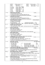
[Auxiliary function setting mode 1]
AT
PV
SV
Selection
• If AT is cancelled during the process,
PID values revert to previous value.
SV (Desired value)
PV
SV
SV
Integral time
PV
SV
Set value
• Set the value with
,
keys.
• PD action when set to 0, and auto-
reset can be performed.
OUT proportional
band
PV
SV
Set value
• Set the value with
,
keys.
• ON/OFF action when set to 0 or 0.0
Derivative time
PV
SV
Set value
• Set the value with
,
keys.
• Setting the value to 0 disables the
function.
OUT proportional
cycle
PV
SV
Set value
• Set the value with
,
keys.
• Not available for DC current output or
when OUT is ON/OFF action
Manual reset
PV
SV
Set value
• Set the value with
,
keys.
• Not available when OUT2 is ON/OFF
action
ARW
PV
SV
Set value
• Set the value with
,
keys.
• Available for PID action
Alarm value
PV
SV
Set value
• Set the value with
,
keys.
• Not available if
is selected
during Alarm action selection
Heater burnout alarm value
PV
.
SV
Set value
• Set the value with
,
keys.
•
Setting the value to 0.0 disables the function.
Reverts to the PV/SV display.
Reverts to PV/SV display.
[Main setting mode]
[Sub setting mode]
PV/SV display
Output MV indication
Press the
key.
Explanation of
key
: This means that
if
is pressed, the set
value is saved, and the
controller proceeds to the
next setting item.
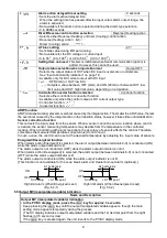
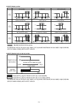
Alarm setting procedure
(Numbers (1) to (6) are indicated on the flowchart.)
(1) [Alarm type]: Select an alarm type
(If an alarm type except for
is selected, items (2) to (6)
are indicated and they can be set if necessary.
(2) [Alarm action Energized/Deenergized]: Select Alarm contact output
ON (Energized:
) or OFF (Deenergized:
).
(3) [Alarm HOLD function]: Select the alarm output Holding or Not Holding.
(4) [Alarm hysteresis]: Set the Alarm hysteresis.
(5) [Alarm action delayed timer]: Set Alarm action delayed time.
(If input enters alarm action range and setting time has passed,
the alarm is activated.)
(6) [Alarm value]: Set action point of Alarm output.
[Note] If an alarm type is changed, the alarm set value
becomes 0 (0.0). Therefore it is necessary to reset it.
Setting items with dotted lines are optional
and they appear only when the options are
added.
Loop break alarm
action time
PV
SV
Set value
• Set the value with
,
keys.
• Setting the value to 0 disables the
function.
Loop break alarm
action span
PV
SV
Set value
• Set the value with
,
keys.
• Setting the value to 0 disables the
function.
Sensor correction
PV
SV
Set value
• Set the value with
,
keys.
Communication protocol
PV
SV
Selection
• Make a selection with
,
keys.
• Not available for
indication
Instrument number
PV
SV
Set value
• Set the value with
,
keys.
Communication speed
PV
SV
Selection
• Make a selection with
,
keys.
Stop bit
PV
SV
Selection
• Make a selection with
,
keys.
• Not available if
is selected
during Communication protocol
selection
Reverts to the PV/SV display.
Parity
PV
SV
Selection
•Make a selection with
,
keys.
• Not available if
is selected
during Communication protocol
selection
(6)
Press the
key
for approx. 3sec.
Press the
key.
Press the
key while holding down the
key.
Press
for approx. 3sec while holding down
.


