


4
Power
supply
Heater
CT
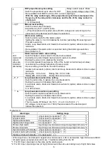
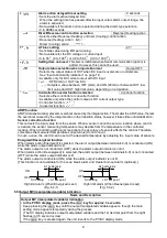
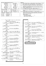
Terminal arrangement
•
OUT
: Control output
•
RELAY : Relay contact output
•
V/A
: DC voltage output/ DC current
output
•
EVT
: Event output [Activated when
Alarm, Loop break alarm or
Heater burnout alarm (option)
is ON]
•
TC
: Thermocouple
•
RTD
: Resistance temperature detector
•
DC
: DC current or DC voltage
For DC current input, 50
shunt
resistor (AKT4810) must be
connected between input terminals.
•
RS-485: Serial communication
(Fig. 4-1)
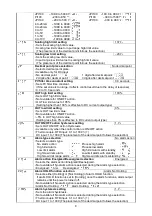
Caution
• Do not leave bits of wire in the KT7 series when wiring, because they could cause a fire or malfunction.
• Insert the connecting cable into the designated connector securely. Otherwise malfunction may occur due
to imperfect contact.
• Connect the AC power wire to the designated terminal as is written in this instruction manual, otherwise
it may burn and damage the KT7 series.
• Tighten the terminal screw with the specified torque. Excessive force could damage the terminal screw
and deface the case.
• To extend a thermocouple’s lead wire, be sure to use a compensating lead wire in accordance with the sensor
input specification. (If any other compensating lead wire is used, a temperature indication error may be caused.)
• Use the 3-wire RTD that corresponds to the sensor input specification of this unit.
• When using DC voltage and current input types, do not confuse the polarity when wiring.
• For a 24V AC/DC power source, do not confuse polarity when using direct current (DC).
• Keep input wires (Thermocouple, RTD, etc) away from power source and load wires to avoid external
interference.
• To prevent the unit from harmful effects of the unexpected level noise, it is recommended that a surge
absorber be installed between the electromagnetic switch coils.
• This unit does not have built-in power switch, circuit breaker or fuse. Therefore, it is necessary to install
them in the circuit externally, near the controller.
(Recommended fuse: Time-lag fuse, rated voltage 250V AC, rated current 2A)
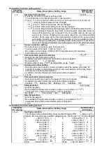
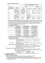
Note:
Tighten the terminal screw properly referring to the table below.
Recommended ferrules
Terminal
number
Terminal
screw
Ferrules with
insulation sleeve
Conductor cross
sections
Tightening torque
Crimping pliers
AI 0.25-8 YE
0.2 to 0.25mm
2
AI 0.34-8 TQ
0.25 to 0.34mm
2
AI 0.5-8 WH
0.34 to 0.5mm
2
AI 0.75-8 GY
0.5 to 0.75mm
2
AI 1.0-8 RD
0.75 to 1.0mm
2
1 to 4
M2.6
AI 1.5-8 BK
1.0 to 1.5mm
2
0.5 to 0.6N
・
m
AI 0.25-8 YE
0.2 to 0.25mm
2
AI 0.34-8 TQ
0.25 to 0.34mm
2
5 to 9
M2.0
AI 0.5-8 WH
0.34 to 0.5mm
2
0.22 to 0.25N
・
m
CRIMPFOX ZA3
CRIMPFOX UD6
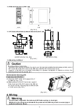
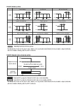
Option: Heater burnout alarm
(1)
This alarm is not available for detecting heater current
under phase control.
(2)
This alarm is not available for detecting 3-phase
heater current.
(3) Use the current transformer (CT) provided, and pass one
lead wire of the heater circuit into the hole of the CT.
(4) When wiring, keep CT wire away from AC sources
or load wires to avoid the external interference.
(5) Solder the wire harness to the CT.
(There is no polarity.)
(Fig. 4-2)
Bottom of the unit
CT input
Communication
C5 (RS-485)
Wire harness
Solder the wire harness to the
CT. (There is no polarity.)
Connector
(Connect to the KT7.)


