


19
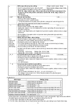
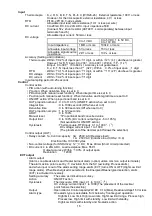
Heater burnout alarm (option), Loop break alarm and Alarm utilize common output terminals.
This option cannot be applied to DC current output type.
Rating
: 5A, 10A, 20A, 50A (Must be specified)
Setting range : 5A, 0.0 to 5.0A (Off when set to 0.0)
10A, 0.0 to 10.0A (Off when set to 0.0)
20A, 0.0 to 20.0A (Off when set to 0.0)
50A, 0.0 to 50.0A (Off when set to 0.0)
Setting accuracy:
5% of the rated value
Action
: ON/OFF action
Output
: Open collector,
Control capacity, 24V DC
0.1A (Max.)
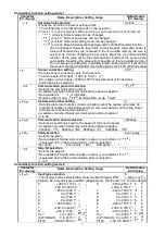
Serial communication (option)
The following operations can be carried out from the external computer.
(1) Reading and setting of SV, PID and various set values
(2) Reading of the PV and action status (3) Change of the functions
Cable length
: Max. communication distance 1000m, Cable resistance; Within 50
Communication interface
: EIA RS-485
Communication method
: Half-duplex communication start-stop synchronous
Communication speed
: 2400, 4800, 9600, 19200bps (Selectable by keypad)
Parity
: Even, Odd and No parity (Selectable by keypad)
Stop bit
: 1, 2 (Selectable by keypad operation)
Communication protocol
: Modbus RTU, Modbus ASCII (Selectable by keypad)
Connectable number of units
: Maximum 31 units to 1 host computer
Communication error detection: Parity, checksum (LRC, CRC)
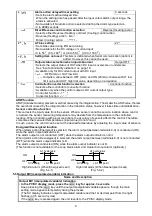
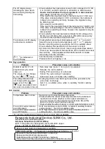
12. Troubleshooting
If any malfunctions occur, refer to the following items after checking the power supply to the controller.
12.1 Indication
Problem
Presumed cause and solution
PV display is indicating
[
].
• Control output OFF function is working.
Press the
key for approx. 1 second to release the function
.
[
] is flashing on the
PV display.
• Burnout of thermocouple, RTD or disconnection of DC voltage (0 to 1V DC)
Change each sensor.
How to check whether the sensor is burnt out
[Thermocouple]
If the input terminals of the instrument are shorted, and if a value
around room temperature is indicated, the instrument is likely to
be operating normally, however, the sensor may be burnt out.
[RTD]
If approx. 100
of resistance is connected to the input terminals
between A-B of the instrument and between B-B is shorted, and
if a value around 0
(32 ) is indicated, the instrument is likely to
be operating normally, however, the sensor may be burnt out.
[DC voltage (0 to 1V DC)]
If the input terminals of the instrument are shorted, and if a
scaling low limit value is indicated, the instrument is likely to be
operating normally, however, the signal wire may be disconnected.
• Check whether the input terminals of thermocouple, RTD or DC voltage
(0 to 1V DC) are securely mounted to the instrument input terminal.
Connect the sensor terminals to the instrument input terminals securely.
[
] is flashing on the
PV display.
• Check whether input signal source for DC voltage (1 to 5V DC) or
DC current (4 to 20mA DC) is disconnected.
How to check whether the input signal wire is disconnected
[DC voltage (1 to 5V DC)]
If the input to the input terminals of the instrument is 1V DC and if
a scaling low limit value is indicated, the instrument is likely to be
operating normally, however, the signal wire may be disconnected.
[DC current (4 to 20mA DC)]
If the input to the input terminals of the instrument is 4mA DC and
if a scaling low limit value is indicated, the instrument is likely to be
operating normally, however, the signal wire may be disconnected.
• Check whether input signal wire for DC voltage (1 to 5V DC) or DC current
(4 to 20mA DC) is securely connected to the instrument input terminals.
• Check if polarity of thermocouple or compensating lead wire is correct.
• Check whether codes (A, B, B) of RTD agree with the instrument terminals.


