


16
Input
Thermocouple
: K, J, R, S, B, E, T, N, PL- , C (W/Re5-26)
External resistance; 100
or less
However, for thermocouple B, external resistance, 40
or less
RTD
: Pt100, JPt100, 3-wire system
Allowable input lead wire resistance (10
or less per wire)
DC current
: 0 to 20mA DC, 4 to 20mA DC, input impedance 50
[Connect 50
shunt resistor (AKT4811, sold separately) between input
terminals 5 and 6]
Allowable input current: 50mA or less
DC voltage
:
0 to 1V DC
0 to 5V DC, 1 to 5V DC,
0 to 10V DC
Input impedance
1M
or more
100k
or more
Allowable input voltage
5V or less
15V or less
Allowable signal source
resistance
2k
or less
100
or less
Accuracy (Setting and Indication)
Thermocouple
: Within
0.2% of input span
1 digit, or within
2
(4 ) whichever is greater
However, for R, S input, 0 to 200
(0 to 400 ): Within
6
(12 )
B input, 0 to 300
(0 to 600 ): Accuracy is not guaranteed.
K, J, E, T, N input, less than 0
(32 ): Within
0.4% of input span
1 digit
RTD
: Within
0.1% of input span
1 digit, or within
1
(2 ) whichever is greater
DC voltage
: Within
0.2% of input span
1 digit
DC current
: Within
0.2% of input span
1 digit
Input sampling period: 0.25 seconds
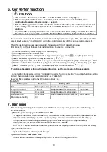
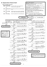
Control
Control action
• PID action (with auto-tuning function)
• PI action: When derivative time is set to 0
• PD action (with manual reset function): When integral time is set to 0
• P action (with manual reset function): When derivative and integral time are set to 0
• ON/OFF action: When proportional band is set to 0
OUT proportional band : 0.0 to 110.0% (ON/OFF action when set to 0.0)
Integral time
: 0 to 1000 seconds (Off when set to 0)
Derivative time
: 0 to 300 seconds (Off when set to 0)
OUT proportional cycle : 1 to 120 seconds
ARW
: 0 to 100%
Manual reset
:
Proportional band converted value
Output limit
: 0 to 100% (DC current output type: –5 to 105%)
(Not available for ON/OFF action)
Hysteresis
: Thermocouple, RTD input: 0.1 to 100.0
( )
DC voltage, current input: 1 to 1000
(The placement of the decimal point follows the selection)
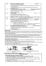
Control output (OUT)
• Relay contact: 1a, Control capacity
3A
250V AC (Resistive load)
1A
250V AC (Inductive load COS ø =0.4)
Electrical life, 100,000 cycles
• Non-contact voltage (for SSR drive): 12
+2
0
V DC
Max. 40mA (Short circuit protected)
• DC current: 4 to 20mA DC, Load resistance; Max. 550
Output accuracy: Within
0.3% of output span
Resolution
: 12000
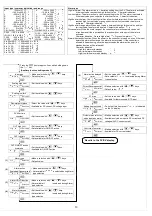
EVT output
• Alarm output
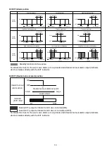
[Alarm, Loop break alarm and Heater burnout alarm (option) utilize common output terminals.]
The alarm action point is set by
deviation from the SV (excluding Process alarm)
and when input is out of the alarm setting range, alarm (EVT) turns ON or OFF (High/Low limit
range alarm). When Deenergized is selected in the Energized/Deenergized selection, alarm
(EVT) is activated conversely.
Setting accuracy
: The same as indication accuracy
Action
: ON/OFF action
Hysteresis
: Thermocouple, RTD input: 0.1 to 100.0 ( )
DC voltage, current input: 1 to 1000 (The placement of the decimal
point follows the selection)
Output
: Open collector, Control capacity 24V DC 0.1A (Max.), Residual voltage:1.5V or less
Alarm type
: One alarm type is selectable from below by front keypad operation:
High limit, Low limit, High/Low limits, High/Low limit range, Process high,
Process low, High limit with standby, Low limit with standby,
High/Low limits with standby and No alarm action


