


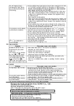

20
The PV display keeps
indicating the value which
was set during Scaling low
limit setting.
• Check whether the input signal source for DC voltage (0 to 5V DC,
0 to 10V DC) and DC current (0 to 20mA DC) is disconnected.
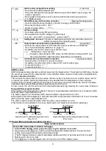
How to check whether the input signal wire is disconnected
[DC voltage (0 to 5V DC, 0 to 10V DC)]
If the input to the input terminals of the instrument is 1V DC and
if the value corresponding to 1V DC is indicated, the instrument
is likely to be operating normally, however, the signal wire may
be disconnected.
[DC current (0 to 20mA DC)]
If the input to the input terminals of the instrument is 1mA DC and
if the value corresponding to 1mA DC is indicated, the instrument
is likely to be operating normally, however, the signal wire may be
disconnected.
• Check whether the input lead wire terminals for DC voltage (0 to
5V DC, 0 to 10V DC) or DC current (0 to 20mA DC) are securely
mounted to the instrument input terminals.
The indication of PV display
is abnormal or unstable.
• Check whether sensor input or temperature unit (
or
) is correct.
Select the sensor input and temperature unit (
or
) properly.
• Sensor correcting value is unsuitable. Set it to a suitable value.
• Check whether the specification of the sensor is correct.
• AC leaks into the sensor circuit. Use an ungrounded type sensor.
• There may be equipment that interferes with or makes noise near
the controller.
Keep equipment that interferes with or makes
noise away from the controller.
[
] is indicated on
the PV display.
• Internal memory is defective.
Please contact our agency or us.
12.2 Key operation
Problem
Presumed cause and solution
Unable to set SV, P, I, D,
proportional cycle, alarm
value, etc.
The values do not change
by the
,
keys.
• Set value lock (Lock 1 or Lock 2) is selected.
Release the lock selection.
• During PID auto-tuning or auto-reset
Cancel the auto-tuning if necessary.
Auto-reset ends 4 minutes after starting.
The setting indication does
not change within the input
range even if the
,
keys are pressed, and
new values are unable to be set.
• Scaling high limit or low limit may be set at the point where the
value does not change.
Set it to a suitable value while in Auxiliary function setting
mode 2.
12.3 Control
Problem
Presumed cause and solution
Temperature does not rise.
• Sensor is out of order. Replace the sensor.
• Check whether the sensor is securely mounted to the instrument
input terminal. Check whether control output terminals are
securely mounted to the actuator input terminals. Mount the
sensor or control output terminal securely.
• Check whether the wiring of sensor or control output terminals is correct.
The control output remains
in an ON status.
• OUT low limit value is set to 100% or higher in Auxiliary function
setting mode 2.
Set it to a suitable value.
The control output remains
in an OFF status.
• OUT high limit value is set to 0% or less in Auxiliary function
setting mode 2.
Set it to a suitable value.
• For all other malfunctions, please contact our main office or dealers.
Panasonic Industrial Devices SUNX Co., Ltd.
http://panasonic.net/id/pidsx/global
Overseas Sales Division (Head Office)
2431-1 Ushiyama-cho, Kasugai-shi, Aichi, 486-0901, Japan
Phone: +81-568-33-7861 FAX: +81-568-33-8591
About our sale network, please visit our website.
PRINTED IN JAPAN
© Panasonic Industrial Devices SUNX Co., Ltd. 2012
Pursuant to the directive 2004/108/EC, article 9(2)
Panasonic Electric Works Europe AG
Rudolf-Diesel-Ring 2 83607 Holzkirchen, Germany
This product has been developed / produced for industrial use only.


