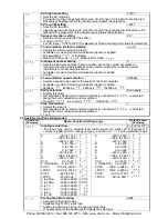
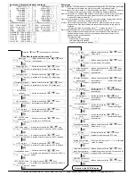


ARW setting
50%
•
Sets ARW (anti-reset windup).
•
Available only when PID is the control action.
•
0 to 100%
OUT1 proportional cycle setting
•
Sets proportional cycle for
OUT1.
Relay contact output: 30 seconds
Non-contact voltage output: 3 seconds
•
Not available for ON/OFF action or DC current output type.
With the relay contact type, if the proportional cycle time is decreased, the fre-
quency of the relay action increases and the life of the relay contact is shortened.
•
1 to 120 seconds
OUT2 proportional cycle setting
3 seconds
•
Sets proportional cycle for OUT2.
•
Not available if OUT2 is ON/OFF action
•
Available only when Heating/Cooling control (option) is applied
• 1 to 120 seconds
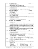
A1 value setting
0
•
Sets action point for A1 output. Setting the value to 0 or 0.0 disables the function (except
process high alarm and process low alarm).
•
Not available if No alarm action is selected during A1 type selection
•
Refer to (Table 5.2-1).
A2 value setting
0
•
Sets action point for A2 output. Setting the value to 0 or 0.0 disables the function (except
process high alarm and process low alarm).
•
Not available if No alarm action is selected during A2 type selection
•
Refer to (Table 5.2-1).
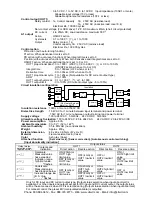
Heater burnout alarm value setting
0.0A
.
and
measured
current
value are
indicated
alternately.
•
Sets the heater current value for Heater burnout alarm.
•
Available only when Heater burnout alarm (option) is added.
•
When OUT1 is OFF, heater current value shows the same value as when OUT1 was on.
•
Setting the value to 0.0 disables the function.
•
It is recommended to set approx. 80% of the heater current value (set value)
considering the voltage fluctuation of power supply.
•
Upon returning to set limits, the alarm will stop.
•
Rating 5A : 0.0 to 5.0A
Rating 10A: 0.0 to 10.0A
Rating 20A: 0.0 to 20.0A Rating 50A: 0.0 to 50.0A
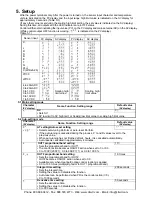
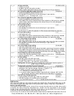
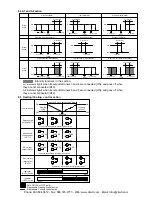
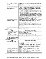
(Table 5.2-1)
Alarm type
Setting range
High limit alarm
– (Input span) to input span
( )
*1
Low limit alarm
– (Input span) to input span
( )
*1
High/Low limits alarm
0 to input span
( )
*1
High/Low limit range alarm
0 to input span ( )
*1
Process high alarm
Input range low limit value to input range high limit value *2
Process low alarm
Input range low limit value to input range high limit value *2
High limit alarm with standby
– (Input span) to input span
( )
*1
Low limit alarm with standby
– (Input span) to input span
( )
*1
High/Low limits alarm with standby 0 to input span
( )
*1
•
When input has a decimal point, negative low limit value is –199.9, and positive high limit value is 999.9.
•
All alarm types except process alarm are deviation setting from the SV.
*1: For DC input, the input span is the same as the scaling span.
*2: For DC input, input range low (or high) limit value is the same as scaling low (or high) limit value.
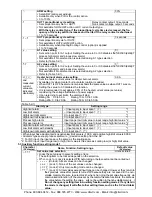
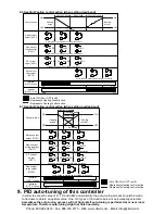
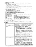
5.3 Auxiliary function setting mode 1
Character
(PV display)
Name, Function, Setting range
Default value
(SV display)
Set value lock selection
Unlock status
• Locks the set values to prevent setting errors.
The setting item to be locked depends on the selection.
• When Lock 1 or Lock 2 is selected, PID Auto-tuning or Auto-reset cannot be carried out.
•
(Unlock) : All set values can be changed.
(Lock 1): None of the set values can be changed.
(Lock 2): Only main setting mode can be changed.
(Lock 3): All set values except Input type can be changed. However, they return to
their previous value after power is turned off because they are not saved in t he non-
volatile memory. Be sure to select Lock 3 when cha nging the set value freque ntly via
communication function. (If the value set by the communication function is the same as
the value before the setting, the value will not be written in the non-volatile memory .)
Do not change any setting item in Auxiliary function setting mode 2. If any item in
the mode is changed, it will affect other setting items such as the SV and Alarm
value.
Phone: 800.894.0412 - Fax: 888.723.4773 - Web: www.clrwtr.com - Email: [email protected]


