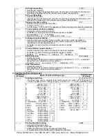
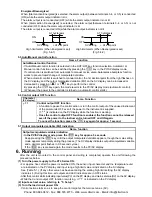
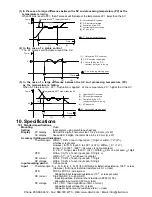

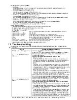
(1) In the case of a large difference between the SV and processing temperature (PV) as the
temperature is rising
When AT bias is set to 20 , the AT process will fluctuate at the temperature 20 lower than the SV.
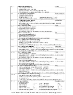
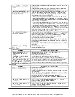
(2) In the case of a stable control
The AT process will fluctuate around the SV.
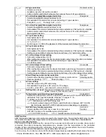
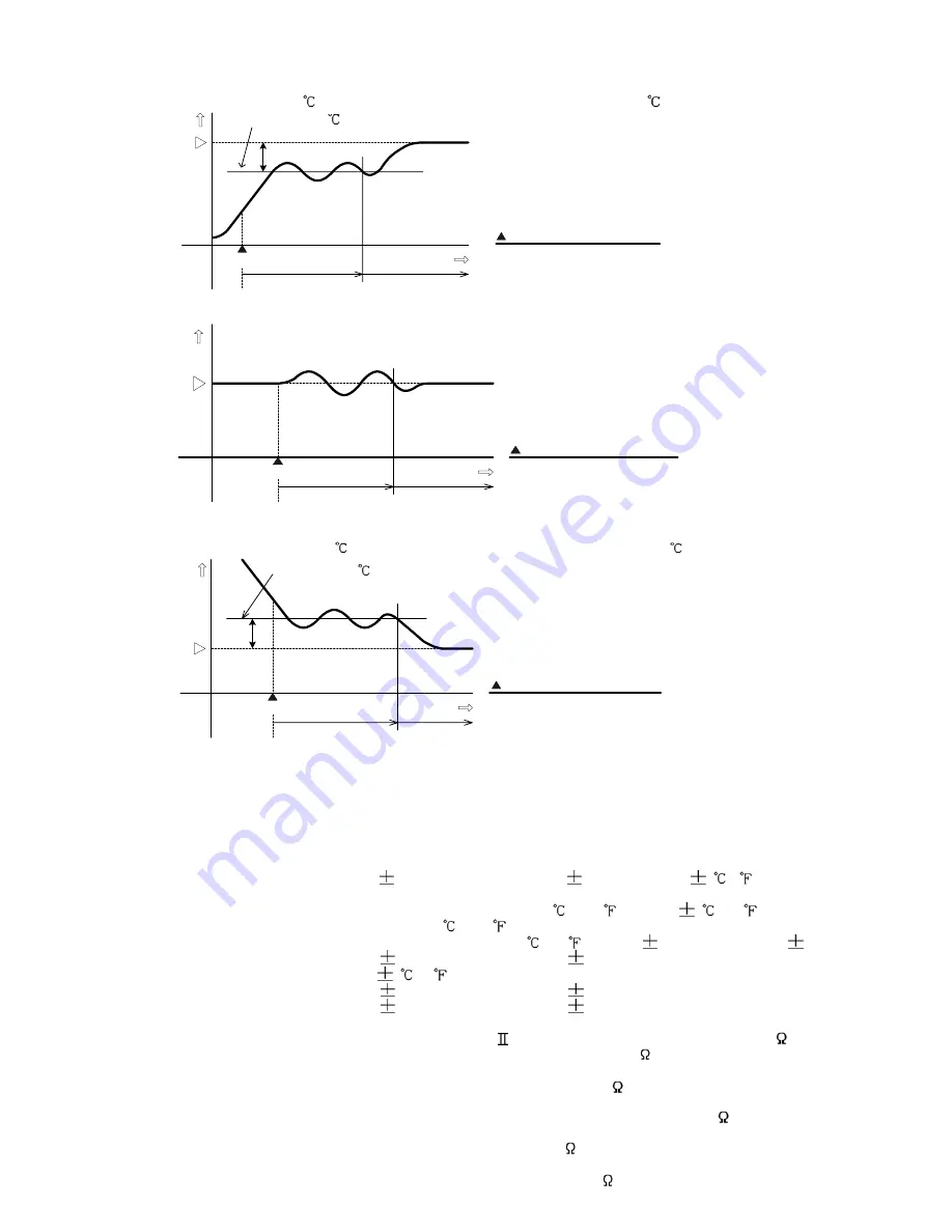
(3) In the case of a large difference between the SV and processing temperature (PV)
as the temperature is falling.
When AT bias is set to 20 , fluctuation is applied at the te mperature 20 higher tha n the SV .
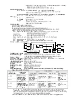
10. Specifications
10.1 Standard specifications
Mounting
: Flush
Setting
: Input system using membrane sheet key
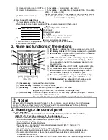
Display
PV display : Red LED 4 digits, character size 10.2 x 4.9 mm (H x W)
SV display
: Green LED 4 digits, character size 8.8 x 4.9 mm (H x W)
Accuracy (Setting and Indication)
:
Thermocouple : Within 0.2% of each input span 1digit, or within 2 (4 ),
whichever is greater
However, for R, S input, 0 to 200
(400 ): Within 6 (12 )
B input, 0 to 300
(600 ): Accuracy is not guaranteed
K, J, E, T, N input, less than 0
(32 ): Within 0.4% of input span 1digit
RTD
: Within 0.1% of each input span 1digit, or
within 1
(2 ), whichever is greater
DC current
: Within 0.2% of each input span 1digit
DC voltage
: Within 0.2% of each input span 1digit
Input sampling period
: 0.25 seconds
Input
Thermocouple :
K, J, R, S, B, E, T, N, PL- , C(W/Re5-26)
External resistance, 100 or less
(However, for B input: External resistance, 40 or less)
RTD : Pt100, JPt100, 3-wire system
Allowable input lead wire resistance (10
or less per wire)
DC current
: 0 to 20mA DC, 4 to 20mA DC
Input impedance: External shunt resistor (AKT4810) 50
Allowable input current (50mA or less)
DC voltage
: 0 to 1V DC Input impedance (1M
or more)
Allowable input voltage (5V or less)
Allowable signal source resistance (2k or less)
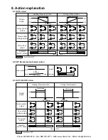
Temp.
Time
AT
(1)
(2)
(3)
:
AT
Auto-tuning starting point
SV
Calculating PID constant
PID constant calculated
Controlled by the PID
constant set by auto-tuning
(3):
(2):
(1):
SV
Temp.
Time
AT
(1)
(2)
(3)
:
AT
Auto-tuning starting point
(1): Calculating PID constant
(2): PID constant calculated
(3): Controlled by the PID
constant set by auto-tuning
(4): AT bias value
(4)
SV
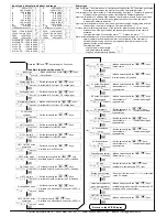
Temp.
Time
AT
(1)
(2)
(3)
(4)
:
AT
Auto-tuning starting point
Calculating PID constant
PID contatnt calculated
Controlled by the PID
constant set by auto-tuning.
AT bias value
(1):
(2):
(3):
(4):
Temperature 20 higher than the SV
Temperature 20 lower than the SV
Phone: 800.894.0412 - Fax: 888.723.4773 - Web: www.clrwtr.com - Email: [email protected]


