

[
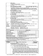
] is flashing on the PV
display.
• Check whether the polarity of thermocouple or compensating lead
wire is correct.
• Check whether codes (A, B, B) of RTD agree with the instrument
input terminals. Ensure that they are wired properly.
The PV display keeps indicating
the value which was set during
scaling low limit value.
• Check whether the input signal source for DC voltage (0 to 5V DC,
0 to 10V DC) and DC current (0 to 20mA DC) is disconnected.
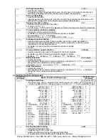
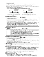
How to check whether the input signal wire is disconnected
[DC voltage (0 to 5V DC, 0 to 10V DC)]
If the input to the input terminal of the instrument is 1V DC and if a
value corresponding to 1V DC is indicated, the instrument is likely to
be operating normally, however, the signal wire may be disconnected.
[DC current (0 to 20mA DC)]
If the input to the input terminal of the instrument is 1mA DC and if a
value corresponding to 1mA DC is indicated, the instrument is likely to
be operating normally, however, the signal wire may be disconnected.
• Check whether the input terminal of DC voltage (0 to 5V DC, 0 to
10V DC) and DC current (0 to 20mA DC) is securely mounted to the
instrument input terminals. Ensure that DC input terminals are
mounted to the instrument input terminals securely.
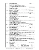
The indication of PV display is
abnormal or unstable.
• Check whether sensor input or temperature unit ( or ) is correct.
Select the sensor input and temperature unit ( or ) properly.
• Sensor correcting value is unsuitable. Set it to a suitable value.
• Check whether the specification of the sensor is correct.
Set the sensor to the proper specification.
• AC leaks into the sensor circuit. Use an ungrounded type sensor.
• There may be equipment that interferes with or makes noise near
the controller.
Keep equipment that interferes with or makes noise away from the
controller.
The PV display is indicating
[
].
• Internal memory is defective.
Contact our agency or us.
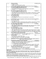
11.2 Key operation
Problem
Presumed cause and solution
• Unable to set the SV, P, I, D,
proportional cycle or alarm
setting
• The values do not change by
,
keys.
• Set value lock (Lock 1 or Lock 2) has been selected.
Release the lock selection.
• During PID auto-tuning or auto-reset.
In the case of PID auto-tuning, cancel auto-tuning.
It takes approximately 4 minutes until auto-reset is finished.
The setting indication does not
change in the input range even if
the
,
keys are pressed,
and new values are unable to be set.
• SV high or low limit value in the Auxiliary function setting mode 1
may be set at the point where the value does not change.
Set it to a suitable value while in the Auxiliary function setting mode 1.
11.3 Control
Problem
Presumed cause and solution
Temperature does not rise.
• Sensor is out of order.
Change the sensor.
• Check whether the sensor is se curely mounted to the instrument
input terminal.
Check whether control output terminals are se curely mounted
to the actu ator input terminals.
Mount the sensor or control output terminal securely.
• Ensure that the wiri ng of sensor or contro l output terminal is
correct.
The control output remains in
an ON status.
• OUT1 or OUT2 low limit value is set to 100% or
higher
during Auxiliary function setting mode 2.
Set it to a suitable value.
The control output remains in
an OFF status.
• OUT1 or OUT2 high limit value is set to 0% or less during
Auxiliary function setting mode 2.
Set it to a suitable value.
Phone: 800.894.0412 - Fax: 888.723.4773 - Web: www.clrwtr.com - Email: [email protected]


