7-39
7.5.2 Communication with External Devices
Programming example of general-purpose serial communication
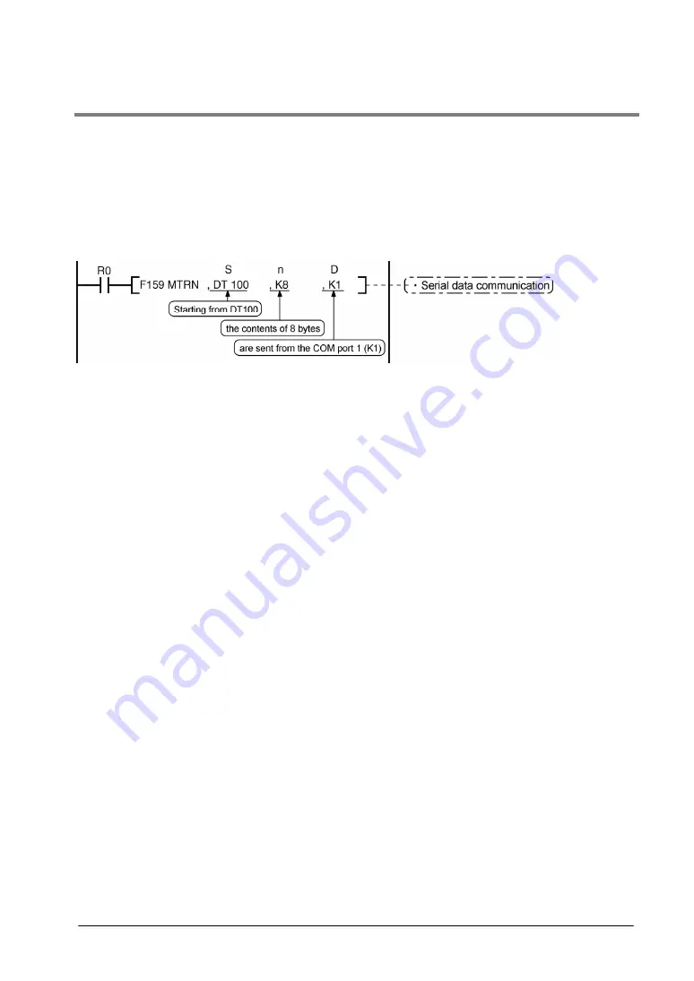
The F159 (MTRN) instruction is used to send and receive data via the specified COM port. F159 (MTRN)
is only used with the FP
Σ
. It is an updated version of F144 (TRNS) and allows multiple communication
ports to be accommodated.
F144 (TRNS) is not available with the FP
Σ
.
F159 (MTRN) instruction
Data is sent and received via the specified COM port .
Devices that can be specified for S:
Devices that can be specified for n:
Devices that can be specified for D:
Only data registers (DT) can be specified as the send buffer.
WX, WY, WR, WL, SV, EV, DT, LD, I (I0 to ID), K, H
Only the K constants (only K1 and K2)
Transmission of data
The amount of data specified by n is sent to the external device from among the data stored in the data
table, starting with the area specified by S, through the COM port specified by D. Data can be sent with
the header and terminator automatically attached. A maximum of 2048 bytes can be sent. When the
above program is run, the eight bytes of data contained in DT101 to DT104 and stored in the send buffer
starting from DT100 are sent from COM1 port.
Reception of data
Reception of data is controlled by turning the “reception done” flags R9038/R9048 on and off. The
received data is stored in the receive buffe specified in the system register. Data can be received when
F159 (MTRN) turns the “reception done” flag off. When the reception of the data is completed (the
terminator is received), the “reception done” flag turns on, and subsequently, receiving data is prohibited.
To receive the next data, execute the F159 (MTRN) instruction and turn the “reception done” flag off to
clear the number of received bytes to 0. To receive data continuously without sending data, clear the
number of transmitted bytes to 0 (set “n” to “K0”), and then execute the F159 (MTRN) instruction.
Содержание FP E Series
Страница 1: ......
Страница 16: ......
Страница 17: ...Chapter 1 Functions and Restrictions of the Unit ...
Страница 28: ...1 12 ...
Страница 29: ...Chapter 2 Specifications and Functions of the Unit ...
Страница 37: ...2 9 Circuit diagram C32 Y0 Y1 Y3 Y4 C28 Y0 Y1 Y3 Y4 Y2 Y5 to YF Y2 Y5 to YB ...
Страница 48: ...2 20 ...
Страница 49: ...Chapter 3 Expansion ...
Страница 56: ...3 8 Terminal layout diagram Note The numbers in the connector are for the first expansion ...
Страница 61: ...Chapter 4 I O Allocation ...
Страница 66: ...4 6 ...
Страница 67: ...Chapter 5 Installation and Wiring ...
Страница 90: ...5 24 ...
Страница 91: ...Chapter 6 High speed counter Pulse Output and PWM Output functions ...
Страница 116: ...6 26 ...
Страница 121: ...6 31 ...
Страница 125: ...6 35 Pulse output diagram ...
Страница 131: ...6 41 ...
Страница 139: ...6 49 ...
Страница 141: ...6 51 ...
Страница 144: ...6 54 Program Continued on the next page ...
Страница 145: ...6 55 ...
Страница 147: ...6 57 Program ...
Страница 151: ...Chapter 7 Communication Cassette ...
Страница 202: ...7 52 Procedure of communication In the following example the Micro Imagechecker is connected to COM1 port ...
Страница 210: ...7 60 The values of DT50 and DT51 are written in DT0 and 1 of PLC ...
Страница 238: ...7 88 ...
Страница 239: ...Chapter 8 Self Diagnostic and Troubleshooting ...
Страница 247: ......
Страница 248: ......
Страница 249: ...Chapter 9 Precautions During Programming ...
Страница 260: ...9 12 Example 2 Using the CT instruction between JP and LBL instructions ...
Страница 268: ...9 20 ...
Страница 269: ...Chapter10 Specifications ...
Страница 286: ......
Страница 287: ...Chapter 11 Dimensions ...
Страница 290: ...11 4 11 1 3 Expansion Unit FPG XY64D2T FPG XY64D2P FPG EM1 ...
Страница 293: ...Chapter 12 Appendix ...
Страница 297: ...12 5 ...
Страница 437: ...12 145 12 7 ASCII Codes ...
Страница 439: ......
Страница 440: ......


