DISASSEMBLY / REASSEMBLY INSTRUCTIONS
MCUK000601C8
Section 4
Issue 1
Service Manual
– 25 –
Revision 0
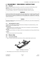
Figure 4.18: Antenna Removal
4.3. Re-assembly
Re-assembly is the reverse of disassembly, except that the Keypad PCB should be located in the chassis guides adjacent to
the base I/O connector before sliding it in to its normal location.
Ensure that the securing screws are not over-tightened as this may affect the operation of the keypad.
10228-1
Содержание EB-GD52
Страница 4: ...Issue 1 iv MCUK000601C8 Revision 0 Service Manual This page is left intentionally blank ...
Страница 81: ... 5 8 7 5 06 0 8 6HFWLRQ VVXH 6HUYLFH 0DQXDO 5HYLVLRQ 5 8 7 5 06 0DLQ 3 RJLF LJXUH 0DLQ 3 5 FLUFXLW GLDJUDP ...
Страница 82: ... 5 8 7 5 06 VVXH 6HFWLRQ 0 8 5HYLVLRQ 6HUYLFH 0DQXDO 0DLQ 3 5 LJXUH 0DLQ 3 RJLF FLUFXLW GLDJUDP ...
Страница 83: ... 5 8 7 5 06 0 8 6HFWLRQ VVXH 6HUYLFH 0DQXDO 5HYLVLRQ H SDG 3 ...
Страница 84: ... 5 8 7 5 06 VVXH 6HFWLRQ 0 8 5HYLVLRQ 6HUYLFH 0DQXDO 7KLV SDJH LV LQWHQWLRQDOO EODQN ...
Страница 85: ... 5 8 7 5 06 0 8 6HFWLRQ VVXH 6HUYLFH 0DQXDO 5HYLVLRQ 0DLQ 3 RJLF LJXUH 0DLQ 3 5 FLUFXLW GLDJUDP ...
Страница 86: ... 5 8 7 5 06 VVXH 6HFWLRQ 0 8 5HYLVLRQ 6HUYLFH 0DQXDO 0DLQ 3 5 LJXUH 0DLQ 3 RJLF FLUFXLW GLDJUDP ...
Страница 87: ... 5 8 7 5 06 0 8 6HFWLRQ VVXH 6HUYLFH 0DQXDO 5HYLVLRQ H SDG 3 ...
Страница 88: ... 5 8 7 5 06 VVXH 6HFWLRQ 0 8 5HYLVLRQ 6HUYLFH 0DQXDO 7KLV SDJH LV LQWHQWLRQDOO EODQN ...

