38
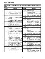
Error Messages
When trouble has occurred in the unit, one of the following error messages will be displayed on the tape
counter.
Error No.
Description
– d –
Condensation (dew) has formed.
E — 00
E — 01
E — 02
E — 11
E — 21
This appears when the cassette down operation fails
to take place even when 4 seconds have elapsed
after the cassette was inserted.
Alternatively, it appears when the cassette fails to be
ejected even when 4 seconds have elapsed after its
ejection operation was performed.
E — 31
This appears when the loading operations fails to be
completed within 4 seconds.
E — 32
This appears when the unloading operations fails to
be completed within 4 seconds.
E — 41
This appears when the FG signal (rotational speed
signal) fails to be output from the cylinder motor.
E — 42
This appears when the PG signal (phase signal) fails
to be output from the cylinder motor.
E — 43
This appears when the cylinder motor speed is
abnormally high.
E — 44
This appears when the cylinder motor speed is
abnormally low.
E — 51
This appears when the FG signal (rotational speed
signal) fails to be output from the capstan motor.
E — 52
This appears when the capstan motor speed is
abnormally high.
Error No.
Description
E — 66
This appears when the start or end processing
operation fails to be completed within 7 seconds.
E — 67
This appears when there is a communication error
between SERVO and AVSYS. There is a problem
with the data.
E — 6A
This appears when there is a communication error
between IF and FRONT.
E — 6B
This appears when there is a communication error
between IF and AVSYS. There is a problem with the
internal reference or external reference.
E — 68
This appears when there is a communication error
between SERVO and AVSYS. The data is fixed to
high or low.
E — 69
This appears when there is a problem in
communication between SERVO and AVSYS when
the power is turned on.
E — 10
E — 80
This appears when there is a problem with the
supply voltage.
E — bA
This appears when the input DC voltage has
dropped below the undercut voltage (approx. 10.6V).
This appears when the reel base which operates in
accordance with the size of the tape has locked up
for more than 2.5 seconds.
E — 53
This appears when the capstan motor speed is
abnormally low.
E — 61
This appears when the supply reel motor has locked
up.
E — 62
This appears when the take-up reel motor has
locked up.
E — 63
This appears when the supply reel motor speed is
abnormally high.
E — 64
This appears when the take-up reel motor speed is
abnormally high.
E — 65
This appears when abnormal tension has been
detected.
E — 09
This appears when the servo has failed to lock for
more than 3 seconds.
If “T&S&R” has been selected as the setup menu
item No.003 setting, “SERVO NOT LOCKED” is
displayed on the third line (amount of remaining tape
line) of the monitor screen.
This appears when there is no head output (due to
clogging, etc.) for more than 3 seconds.
“L” is displayed on the first line (counter line) of the
monitor screen.
If “T&S&R” has been selected as the setup menu
item No.003 setting, “LOW RF” is displayed on the
third line (amount of remaining tape line) of the
monitor screen.
This appears when the error rate has deteriorated
(when the channel condition lamps have turned red).
If “T&S&R” has been selected as the setup menu
item No.003 setting, “HIGH ERROR RATE” is
displayed on the third line (amount of remaining tape
line) of the monitor screen.
This appears when a blank portion on the tape has
been detected.
“N” is displayed on the first line (counter line) of the
monitor screen.
If “T&S&R” has been selected as the setup menu
item No.003 setting, “NO RF” is displayed on the
third line (amount of remaining tape line) of the
monitor screen.
When all the following conditions are satisfied, the
part of the tape concerned is recognized as a blank
part.
O
When there is no output from any of the heads
O
When the playback data cannot be read
O
When there is no CTL signal
This appears when the fan motor has stopped.
“S” is displayed on the first line (counter line) of the
monitor screen.
If “T&S&R” has been selected as the setup menu
item No.003 setting, “FAN STOP” is displayed on
the third line (amount of remaining tape line) of the
monitor screen.
The power will be automatically turned off if the fan
remains stopped for more than 5 minutes or so.
Содержание AJ-D95
Страница 43: ......

