42
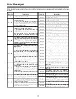
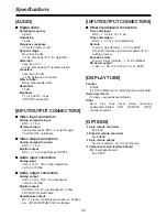
[AUDIO]
$
Digital audio
Sampling frequency
48 kHz
Quantizing
16 bits
Frequency response
20 Hz to 20 kHz ±1 dB
Dynamic range
More than 85 dB
(1 kHz, emphasis OFF, “A” weighted)
Distortion
Less than 0.1%
(1 kHz, emphasis OFF, reference level)
Crosstalk
Less than –80 dB
(1 kHz, between 2 channels)
Wow & flutter
Below measurable limits
Headroom
20 dB
Emphasis
T1 = 50 µs/T2 = 15 µs
(ON/OFF switchable)
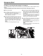
[INPUT/OUTPUT CONNECTORS]
[DISPLAY TUBE]
$
Video input connectors
Analog composite input
BNC
a
1, 75
Ω
Reference input
Analog composite, BNC
a
2 (loop-through),
75
Ω
ON/OFF switchable
$
Video output connectors
Analog composite output
BNC
a
1, 75
Ω
Monitor output
BNC
a
1, 75
Ω
, superimpose ON/OFF
$
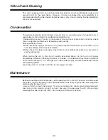
Audio input connectors
Analog input
XLR
a
2 (CH1, CH2), high impedance,
+4/0/–3/–20 dBu
$
Audio output connectors
Analog output
XLR
a
2 (CH1, CH2), low impedance,
+4/0/–3/–20 dBu
Monitor output
PHONO
a
2 (L, R), low impedance, 0 dBu,
CH1/MIX/CH2 switchable
Headphones output
M3
a
1, stereo, variable level (maximum –20 dBu),
8
Ω
, CH1/MIX/STEREO/CH2 switchable
Counter
8 digits
(CTL/TC/UB/amount of remaining tape switchable)
Audio level meter
17 steps + excessive level display
Other
Servo lock, tape travel status, recording
enabled/prohibited, SCH, REMOTE, WIDE,
channel condition
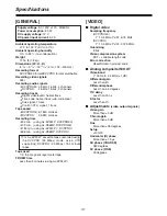
[OPTIONS]
O
9-pin remote controller
AJ-A95P
O
Encoder remote controller
AU-ER65B
O
9-pin remote cables
AU-C5 (5 meters), AU-C10 (10 meters)
O
Component serial interface board
(SDI input/output board)
AJ-YA95P
[INPUT/OUTPUT CONNECTORS]
$
Other input/output connectors
Time code input
BNC
a
1, 0.5 to 8 V
P-P
, 8 k
Ω
Time code output
BNC
a
1, 2.0 V
P-P
, low impedance
Remote
D-sub, 9 pins (female)
a
1, for AJ-A95P
RS-422A interface standard complied with (no
editing function)
Encoder remote
D-sub, 15 pins (female)
a
1, for AU-ER65B
DC power output
4 pins
a
1, DC 12 V, 250 mA, for AJ-A95P
Specifications
Содержание AJ-D95
Страница 43: ......

