MECH-9
1-9. LISTA Linearity Adjustment
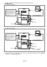
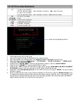
TP
In case of use VFK1409A
F2
: ATF-ERR (VFK1409A),
TP2
: TRG/HSW (VFK1409A),
GND
: GND (VFK1409A)
In case of use VFK1409S
F2
: ATF-ERR (VFK1409S),
TP2
: TRG/HSW (VFK1810),
GND
: GND (VFK1409S)
ADJ.
S1 and T1 Post Height
VTR MODE
PLAY
ADJ. MODE
Refer to below explanation
TAPE
VFM3000LS (DV LISTA)
TOOL
VFK1899 : Post Driver
SPEC.
Linearity : less than 3
µ
m
1.
Set the camera recorder to VCR mode.
2.
Insert the DV Alignment Tape (VFM3000LS) to the camera recorder.
3.
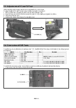
Open the cassette cover follow the item
“1-3. Adjustment of S1 and T2 Post”
in this section.
4.
Press the button in order of
“ADUB button”
→
“STOP button”
→
“MODE CHK button”
→
“MENU button”
,
to open the
“VCR FUNCTION MENU”
.
5.
Select the item
“ADJUST MENU”
and press the SET(STILL) button to open the
“ADJUST MENU”
.
6.
Select the item
“LINEARITY”
and press the SET(STILL) button.
7.
Select the item
“ON”
and press the SET(STILL) button, then message
“NOW SERVO ADJUST PUSH MENU
TO RETURN”
appears on screen and press the PLAY button to playback the tape.
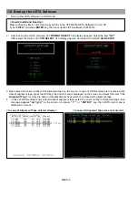
8. Select
item
“<2> Linearity Measurement”
on the LISTA main menu, and press
“ENTER”
, then the Linearity
Waveform appears.
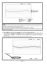
9. When the waveform as shown in figure below is displayed on the screen, press the
“BS (Back Space)”
key
for display the waveform positioned at the center of the scale on screen. Adjust S1 and T1 post height by using
the post driver so that the linearity waveform is becomes flat as possible, and it should be within specification.
(Adjust linearity waveform in the red dot line on the screen.)
Select at Linearity Measurement.
Содержание AGDVX100BP - DVC CAMCORDER
Страница 3: ...3...
Страница 4: ...4 AG DVX100BE...
Страница 5: ...5...
Страница 7: ...7 AG DVX100BP...
Страница 8: ...8 AG DVX100BE...
Страница 9: ...9...
Страница 10: ...10...
Страница 11: ...MHNK150 0123457F6S8P...
Страница 154: ...E14 1 2 3 9 4 5 6 7 8 102 102 101 101 MPL 7 LCD PARTS ASSEMBLY...


