background image

6;6<

Order Placement Recommendations and Considerations


The Products and Specifications listed in this document are subject to change (including  


specifications, manufacturing facility and discontinuing the Products) as occasioned by the 


improvements of Products. Consequently, when you place orders for these Products, Panasonic 


Industrial Devices SUNX asks you to contact one of our customer service representatives and 


check that the details listed in the document are commensurate with the most up-to-date  


information. 


[Safety precautions] 


Panasonic Industrial Devices SUNX is consistently striving to improve quality and reliability. 


However, the fact remains that electrical components and devices generally cause failures  


at a given statistical probability. Furthermore, their durability varies with use environments  


or use conditions. In this respect, check for actual electrical components and devices under  


actual conditions before use. Continued usage in a state of degraded condition may cause the  


deteriorated insulation. Thus, it may result in abnormal heat, smoke or fire. Carry out safety  


design and periodic maintenance including redundancy design, design for fire spread prevention, 


and design for malfunction prevention so that no accidents resulting in injury or death, fire  


accidents, or social damage will be caused as a result of failure of the Products or ending  


life of the Products. 


The Products are designed and manufactured for the industrial indoor environment use. Make


sure standards, laws and regulations in case the Products are incorporated to machinery, system,


apparatus, and so forth. With regard to the mentioned above, confirm the conformity of the


Products by yourself.

Do not use the Products for the application which breakdown or malfunction of Products may 


cause damage

to the body or property.

i) usage intended to protect the body and ensure security of life
ii)application which the performance degradation or quality problems, such as breakdown,

of the Products

may directly result in damage to the body or property


It is not allowed the use of Products by incorporating into machinery and systems indicated


below because

the conformity, performance, and quality of Products are not guaranteed under


such usage.

i) transport machinery (cars, trains, boats and ships, etc.)
ii) control equipment for transportation
iii) disaster-prevention equipment / security equipment
iv) control equipment for electric power generation
v) nuclear control system
vi) aircraft equipment, aerospace equipment, and submarine repeater
vii) burning appliances
viii) military devices
ix) medical devices

ق

except for general controls

ك

x) machinery and systems which especially require the high level of reliability and safety

[Acceptance inspection] 


In connection with the Products you have purchased from us or with the Products delivered  

to your premises, please perform an acceptance inspection with all due speed and, in connection 
with the handling of our Products both before and during the acceptance inspection, please  
give full consideration to the control and preservation of our Products. 

[Warranty period] 


Unless otherwise stipulated by both parties, the warranty period of our Products is

 3 years

after the purchase by you or after their delivery to the location specified by you. 
The consumable items such as battery, relay, filter and other supplemental materials are excluded 
from the warranty. 

[Scope of warranty] 


In the event that Panasonic Industrial Devices SUNX confirms any failures or defects of  

the Products by reasons solely attributable to Panasonic Industrial Devices SUNX during the  
warranty period, Panasonic Industrial Devices SUNX shall supply the replacements of the Products, 
parts or replace and/or repair the defective portion by free of charge at the location where  
the Products were purchased or delivered to your premises as soon as possible. 


However, the following failures and defects are not covered by warranty and we are not responsible 

for such failures and defects.  

(1) When the failure or defect was caused by a specification, standard, handling method,

etc. which was specified by you. 

(2) When the failure or defect was caused after purchase or delivery to your premises by

an alteration in construction, performance, specification, etc. which did not involve
us.

(3) When the failure or defect was caused by a phenomenon that could not be predicted by

the technology at purchasing or contracted time.

(4) When the use of our Products deviated from the scope of the conditions and environment

set forth in the instruction manual and specifications.

(5) When, after our Products were incorporated into your products or equipment for use, damage

resulted which could have been avoided if your products or equipment had been equipped
with the functions, construction, etc. the provision of which is accepted practice in
the industry.

(6) When the failure or defect was caused by a natural disaster or other force majeure.

(7) When the equipment is damaged due to corrosion caused by corrosive gases etc. in the

surroundings.

The above terms and conditions shall not cover any induced damages by the failure or defects 

of the Products, 


and not cover your production items which are produced or fabricated by using

the Products. In any case, our responsibility for compensation is limited to the amount paid 
for the Products. 

[Scope of service] 


The cost of delivered Products does not include the cost of dispatching an engineer, etc. 


In case any such service is needed, contact our sales representative. 

3DQDVRQLF,QGXVWULDO'HYLFHV ㄟㄡㄚㄤ &R/WG

WUME-FPXHAIO-01

Содержание AFPXHEAD4

Страница 1: ...Programmable Controller FP XH Expansion Analog Unit User s Manual Applicable models AFPXHEAD4 AFPXHEAD8 AFPXHEDA4 AFPXHEA21 WUME FPXHAIO 01 2022 2 panasonic net id pidsx global...

Страница 2: ...MEMO 2 WUME FPXHAIO 01...

Страница 3: ...rpose of use Manual name Manual code FP XH Control Unit FP XH User s Manual Basic Edition WUME FPXHBAS FP XH Programming Manual WUME FPXHPGR Positioning Function PWM Output High speed Counter Function...

Страница 4: ...characteristics and performance values of the product Do not disassemble or modify this product Doing so may result in abnormal heat generation or smoke generation Do not touch any terminals while th...

Страница 5: ...Indicates operation procedures WUME FPXHAIO 01 v...

Страница 6: ...MEMO vi WUME FPXHAIO 01...

Страница 7: ...Other Devices 2 4 2 2 2 Terminal Layout AFPXHEAD4 AFPXHEAD8 2 4 2 2 3 Terminal Layout AFPXHEDA4 2 5 2 2 4 Terminal Layout AFPXHEA21 2 7 2 3 Wiring to the Connector 2 8 2 3 1 Suitable Parts and Tools...

Страница 8: ...mes 64 times 128 times 5 2 5 1 3 Enabling Averaging Processing Setting 5 3 5 2 Disconnection Detection 5 5 6 Troubleshooting 6 1 6 1 What to Do If an Error Occurs Analog Input 6 2 6 1 1 Failure in Rea...

Страница 9: ...1 3 1 2 1 Expansion to the FP XH Control Unit 1 3 1 2 2 Restrictions on Using the FP X Expansion FP0 Adapter 1 3 1 3 Names and Functions of Parts 1 5 1 3 1 Analog Input Unit AFPXHEAD4 1 5 1 3 2 Analog...

Страница 10: ...A21 1 1 2 Expansion Cables Applicable cables An 8 cm expansion cable is provided with the Expansion Unit When the expansion cable is used an I O check error may occur due to noise etc In such a case i...

Страница 11: ...9F WY50 to WY59 4th Expansion Unit X600 to X69F WX60 to WX69 Y600 to Y69F WY60 to WY69 5th Expansion Unit X700 to X79F WX70 to WX79 Y700 to Y79F WY70 to WY79 6th Expansion Unit X800 to X89F WX80 to WX...

Страница 12: ...n be connected when using the FP X Expansion FP0 Adapter 3 FP X Expansion FP0 Adapter Connect it to the right of the FP XH Expansion Analog Unit Only one unit can be connected 4 FP0 Expansion Unit Up...

Страница 13: ...ed to connect analog input devices CH0 to CH3 5 Terminator setting DIP switch Turn ON all the switches on the DIP switch for the terminal Expansion Unit Turn OFF all the switches on the DIP switch for...

Страница 14: ...r setting DIP switch Turn ON all the switches on the DIP switch for the terminal Expansion Unit Turn OFF all the switches on the DIP switch for the Expansion Units other than the terminal Expansion Un...

Страница 15: ...or setting DIP switch Turn ON all the switches on the DIP switch for the terminal Expansion Unit Turn OFF all the switches on the DIP switch for the Expansion Units other than the terminal Expansion U...

Страница 16: ...CH0 to CH1 and an analog output device CH0 5 Terminator setting DIP switch Turn ON all the switches on the DIP switch for the terminal Expansion Unit Turn OFF all the switches on the DIP switch for t...

Страница 17: ...al Layout 2 3 2 2 Wiring the Analog I O 2 4 2 2 1 Connecting to Other Devices 2 4 2 2 2 Terminal Layout AFPXHEAD4 AFPXHEAD8 2 4 2 2 3 Terminal Layout AFPXHEDA4 2 5 2 2 4 Terminal Layout AFPXHEA21 2 7...

Страница 18: ...LC Power supply sequence The power supply sequence should be set up so that the power supply of the PLC turns off before the power supplies for input and output If the power supplies for input and out...

Страница 19: ...2 1 3 Terminal Layout Power supply terminal 24V 0V 1 2 3 Pin No Name Function 1 24 V Power supply input 2 0 V Power supply input 3 GND Power supply GND 2 1 Wiring the Power Supply WUME FPXHAIO 01 2 3...

Страница 20: ...se double core twisted pair shielded wires It is recommended to ground them However depending on the conditions of the external noise it may be better not to ground the shielding Do not place the anal...

Страница 21: ...XHEAD8 only VI4 COM VI5 COM COM COM VI6 VI7 CH4 CH5 CH6 CH7 1 2 3 4 5 6 7 8 Pin No Name Function Channel 1 VI4 Voltage current signal input CH4 2 COM Input common 3 VI5 Voltage current signal input CH...

Страница 22: ...terminals are connected within the unit Analog terminal block 2 COM COM CH2 CH3 NC V3 I3 V2 I2 NC 1 2 3 4 5 6 7 8 Pin No Name Function Channel 1 V2 Voltage signal output CH2 2 I2 Current signal output...

Страница 23: ...signal input Input CH0 2 COM Input common 3 VI1 Voltage current signal input Input CH1 4 COM Input common 5 NC Not used 6 V0 Voltage signal output Output CH1 7 I0 Current signal output 8 COM Output c...

Страница 24: ...ntact Co Ltd 0 25 mm2 AWG24 AI 0 25 6 YE 0 50 mm2 AWG20 AI 0 5 6 WH 0 75 mm2 AWG18 AI 0 75 6 GY 1 00 mm2 AWG18 AI 1 6 RD Crimping tool dedicated to rod terminals Manufacturer Model number Product No P...

Страница 25: ...tion number Phoenix Contact Co Ltd SZS 0 4x2 5 1205037 The following precautions should be observed to avoid broken or disconnected wires When removing the wire s sheath be careful not to scratch the...

Страница 26: ...MEMO 2 10 WUME FPXHAIO 01...

Страница 27: ...es 3 8 3 3 2 Input Range Setting Area 3 8 3 3 3 Averaging Processing Setting 3 10 3 3 4 Output Range Setting Area 3 11 3 4 Analog Input Functions 3 12 3 4 1 Analog Input Specifications 3 12 3 4 2 Anal...

Страница 28: ...X70 WX80 WX90 WX100 Analog input value CH1 WX31 WX41 WX51 WX61 WX71 WX81 WX91 WX101 Analog input value CH2 WX32 WX42 WX52 WX62 WX72 WX82 WX92 WX102 Analog input value CH3 WX33 WX43 WX53 WX63 WX73 WX83...

Страница 29: ...t value CH4 WX34 WX44 WX54 WX64 WX74 WX84 WX94 WX104 Analog input value CH5 WX35 WX45 WX55 WX65 WX75 WX85 WX95 WX105 Analog input value CH6 WX36 WX46 WX56 WX66 WX76 WX86 WX96 WX106 Analog input value...

Страница 30: ...unit 4th unit 5th unit 6th unit 7th unit 8th unit I O numbers occupied by the unit WY30 WY39 WY40 WY49 WY50 WY59 WY60 WY69 WY70 WY79 WY80 WY89 WY90 WY99 WY100 WY109 Analog output value CH0 WY30 WY40...

Страница 31: ...WX74 WX84 WX94 WX104 Output contact WY Item Expansion location 1st unit 2nd unit 3rd unit 4th unit 5th unit 6th unit 7th unit 8th unit I O numbers occupied by the unit WY30 WY39 WY40 WY49 WY50 WY59 WY...

Страница 32: ...on is valid only when the range setting is set to 4 to 20 mA or 1 to 5 V If a disconnection state is detected H8000 K 32768 is stored The detection level for disconnection detection is as follows Inpu...

Страница 33: ...PXHEA21 CH0 Analog output status Bit OFF Normal Bit ON Error Operation of the analog output status error An error is notified when the data stored in the analog output values CH0 to CH3 exceeds the se...

Страница 34: ...0 mA K0 to K 32000 For 4 to 20 mA K0 to K 25600 I O allocation Channel Expansion location 1st unit 2nd unit 3rd unit 4th unit 5th unit 6th unit 7th unit 8th unit CH0 WY30 WY40 WY50 WY60 WY70 WY80 WY90...

Страница 35: ...nit 7th unit 8th unit Input range setting area 1 CH0 to CH3 WY30 WY40 WY50 WY60 WY70 WY80 WY90 WY100 Input range setting area 2 CH4 to CH7 WY31 WY41 WY51 WY61 WY71 WY81 WY91 WY101 I O contents Input r...

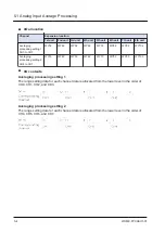
Страница 36: ...n Channel Expansion location 1st unit 2nd unit 3rd unit 4th unit 5th unit 6th unit 7th unit 8th unit Averaging processing setting 1 CH0 to CH3 WY32 WY42 WY52 WY62 WY72 WY82 WY92 WY102 Averaging proces...

Страница 37: ...to 10 V H5 5 to 5 V H6 1 to 5 V H7 4 to 20 mA H0 H8 to F Do not use the analog input I O allocation Channel Expansion location 1st unit 2nd unit 3rd unit 4th unit 5th unit 6th unit 7th unit 8th unit C...

Страница 38: ...al input range 10 to 10 V DC 5 to 5 V DC K 32000 to K 32000 0 to 10 V DC 0 to 5 V DC K 0 to K 32000 1 to 5 V DC K 0 to K 25600 0 to 20 mA K 0 to K 32000 4 to 20 mA K 0 to K 25600 Conversion speed 1 ms...

Страница 39: ...lue is entered in the Input range setting area using the user program the analog input range is set in the unit When H1 to H7 is entered in the Input range setting area the analog input is started If...

Страница 40: ...r each channel data is allocated from the lower level in the order of CH0 CH1 CH2 and CH3 Input range setting area 2 The range setting data for each channel data is allocated from the lower level in t...

Страница 41: ...each input range are as follows Input range Digital conversion value For 10 to 10 V 5 to 5 V K 32000 to K 32000 For 0 to 10 V 0 to 5 V K0 to K 32000 For 1 to 5 V K0 to K 25600 For 0 to 20 mA K0 to K...

Страница 42: ...3 4 Analog Input Functions 3 16 WUME FPXHAIO 01...

Страница 43: ...5 V DC K 0 to K 25600 0 to 20 mA K 0 to K 32000 4 to 20 mA K 0 to K 25600 Conversion speed 1 ms all channels Output impedance voltage output 0 5 or less Maximum output current voltage output 10 mA Ou...

Страница 44: ...he user program to set the 10 to 10 V range to CH0 and CH1 and the 4 to 20 mA range to CH2 and CH3 R0 F0 MV H7744 WY36 Output range setting value H1 0 to 10 V H2 0 to 5 V H3 0 to 20 mA H4 10 to 10 V H...

Страница 45: ...ersion values Digital conversion values for each output range are as follows Output range Digital conversion value For 10 to 10 V 5 to 5 V K 32000 to K 32000 For 0 to 10 V 0 to 5 V K0 to K 32000 For 1...

Страница 46: ...3 5 Analog Output Functions 3 20 WUME FPXHAIO 01...

Страница 47: ...4 Analog I O Conversion Characteristics 4 1 Input Conversion Characteristics 4 2 4 2 Output Conversion Characteristics 4 6 WUME FPXHAIO 01 4 1...

Страница 48: ...the rated range Analog input value Converted value 10 V or more 32 000 10 V or less 32 000 Voltage input range 5 to 5 V Input range 5 to 5 V Analog input value V Digital conversion value K 5 32 000 2...

Страница 49: ...ange Analog input value Converted value 10 V or more 32 000 0 V or less 0 Voltage input range 0 to 5 V Input range 0 to 5 V Analog input value V Digital conversion value K 5 32 000 4 25 600 3 19 200 2...

Страница 50: ...og input value Converted value 5 V or more 25 600 1 V or less 0 Current Input range 0 to 20 mA Input range 0 to 20 mA Analog input value mA Digital conversion value K 20 32 000 16 25 600 12 19 200 8 1...

Страница 51: ...Analog input value mA Digital conversion value K 20 25 600 16 19 200 12 12 800 8 6 400 4 0 0 0 When exceeding the rated range Analog input value Converted value 20 mA or more 25 600 4 mA or less 0 4...

Страница 52: ...value Analog output value 32 640 or more Output at 10 2 V 32 640 or less Output at 10 2 V Voltage output range 0 to 10 V Output range 0 to 10 V Digital input value K Analog output value V 32 000 10 25...

Страница 53: ...log output value 32 640 or more Output at 5 1 V 640 or less Output at 0 1 V Voltage output range 1 to 5 V Output range 1 to 5 V Digital input value K Analog output value V 25 600 5 19 200 4 12 800 3 6...

Страница 54: ...ue 32 640 or more Output at 5 1 V 32 640 or less Output at 5 1 V Current output range 0 to 20 mA Output range 0 to 20 mA Digital input value K Analog output value mA 32 000 20 25 600 16 19 200 12 12 8...

Страница 55: ...put value K Analog output value mA 25 600 20 19 200 16 12 800 12 6 400 8 0 4 When exceeding the rated range Digital input value Analog output value 26 240 or more Output at 20 4 mA 640 or less Output...

Страница 56: ...MEMO 4 10 WUME FPXHAIO 01...

Страница 57: ...Analog Input Average Processing 5 2 5 1 1 Moving average 10 times 5 2 5 1 2 Number of averaging times 64 times 128 times 5 2 5 1 3 Enabling Averaging Processing Setting 5 3 5 2 Disconnection Detection...

Страница 58: ...and the remaining eight values are averaged and stored in the external input area WX If a fraction results from the calculation it is rounded off Operation Timing chart Analog input value Read timing...

Страница 59: ...tion is carried out with the average of data for 64 times or 128 times Method for setting the number of averaging times The number of averaging times can be changed by being written to the output rela...

Страница 60: ...tting 2 CH4 to CH7 WY33 WY43 WY53 WY63 WY73 WY83 WY93 WY103 I O contents Averaging processing setting 1 The range setting data for each channel data is allocated from the lower level in the order of C...

Страница 61: ...detection The disconnection detection is valid only when the analog input range setting is set to 4 to 20 mA or 1 to 5 V If a disconnection state is detected H8000 K 32768 is stored in the Analog inpu...

Страница 62: ...MEMO 5 6 WUME FPXHAIO 01...

Страница 63: ...Input Data 6 2 6 1 2 Unstable Analog Input Values 6 2 6 1 3 No Proper Conversion Values Obtained with Current Input 6 2 6 2 What to Do If an Error Occurs Analog Output 6 3 6 2 1 Unstable Analog Output...

Страница 64: ...ot placed close to AC lines or high tension lines or bundled with the lines 3 Check that there are no power lines high tension lines high capacity relays or noise generating equipment such as inverter...

Страница 65: ...program again 6 2 2 Unchanged Analog Output Value Situation The analog output value remains unchanged Solution 1 Check that the unit is in RUN mode 2 Check again that I O allocations are correct 3 Che...

Страница 66: ...pply to the FP XH Expansion Analog Unit is turned OFF or the expansion cable is disconnected Use the special data registers DT90010 and DT90011 to check the Expansion Unit whose connection state has b...

Страница 67: ...7 Specifications 7 1 General Specifications 7 2 7 2 Analog Input Specifications 7 3 7 3 Analog Output Specifications 7 4 7 4 External Dimensions Unit mm 7 5 WUME FPXHAIO 01 7 1...

Страница 68: ...earth terminals 500 V AC for 1 minute Isolation resistance Test voltage 500 V DC Between analog I O terminal and power supply terminal function earth terminals 100 M or more Vibration resistance 5 to...

Страница 69: ...ess at 0 to 55 Current 0 3 F S or less at 25 0 6 F S or less at 0 to 55 Input impedance Voltage Approx 1 M Current Approx 250 Absolute max input Voltage input 15 to 15 V DC voltage input Current input...

Страница 70: ...to 20 mA K 0 to K 25600 Conversion speed 1 ms all channels Output impedance voltage output 0 5 or less Maximum output current voltage output 10 mA Output allowable load resistance current output 500...

Страница 71: ...7 4 External Dimensions Unit mm AFPXHEAD4 AFPXHEA21 82 60 90 AFPXHEAD8 AFPXHEDA4 60 90 82 7 4 External Dimensions Unit mm WUME FPXHAIO 01 7 5...

Страница 72: ...MEMO 7 6 WUME FPXHAIO 01...

Страница 73: ...Record of Changes The manual code is shown at the bottom of the cover page Date Manual code Record of changes Feb 2022 WUME FPXHAIO 01 1st edition WUME FPXHAIO 01...

Страница 74: ...the high level of reliability and safety Acceptance inspection In connection with the Products you have purchased from us or with the Products delivered to your premises please perform an acceptance...

Страница 75: ...MEMO WUME FPXHAIO 01...

Страница 76: ...ju Road Suzhou New District Jiangsu China Telephone 86 512 6843 2580 panasonic net id pidsx global For our sale network please visit our website Panasonic Industrial Devices SUNX Co Ltd 2022 February...

Отзывы: